




Contents: Examination ↓ Grinding ↓
Intake valve seat profile
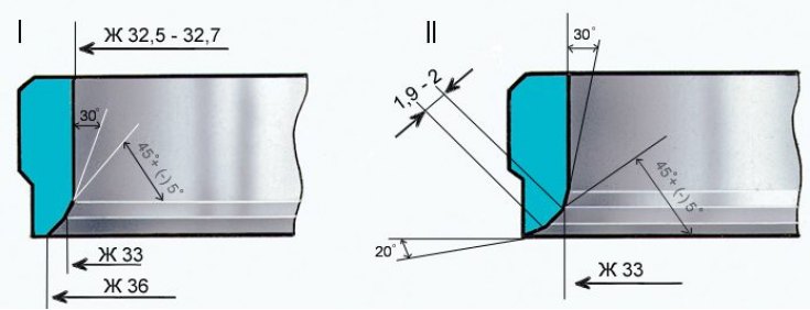
I - new saddle; II – saddle after repair
Exhaust valve seat profile
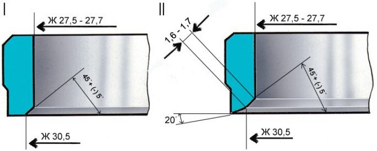
I - new saddle; II – saddle after repair
The shape of the valve seat chamfers is shown in the figures.
Examination
On the working chamfers of the saddles (valve contact area) there should be no pitting, corrosion or damage. Minor damage can be eliminated by grinding the seats. In doing so, remove as little metal as possible. Grinding can be done manually or with a grinding machine.
The text is on the website (VazBook.ru)
Grinding
1. Mount the head on the support A.60353, insert the rod A.94059 into the valve guide sleeve and clean the seat chamfers from carbon deposits using countersinks A.94031 and A.94092 for the exhaust valve seats and countersinks A.94003 and A.94101 for the intake valve seats. The countersinks are put on the spindle A.94058 and centered using the guide rod A.94059.
Attention! Rods A.94059 are available in two different diameters: A.94059/1 – for intake valve guide bushings and A.94059/2 – for exhaust valve guide bushings.
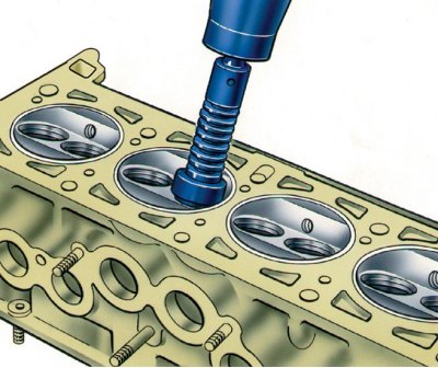
2. Place the spring A.94069/5 on the guide rod A.94059, install the conical circle A.94078 for the exhaust valve seats or the circle A.94100 for the intake valve seats on the spindle A.94069, secure the spindle in a grinder and grind the valve seat.
3. At the moment of contact of the wheel with the saddle the machine should be switched off, otherwise vibration will occur and the chamfer will be incorrect. It is recommended to correct the wheel with a diamond more often.
4. For the exhaust valve seats, bring the working chamfer width to the values shown in Fig. Exhaust valve seat profile, using countersink A.94031 (angle 200), and countersink A.94092, which removes work hardening on the inner diameter. Countersinks are placed on spindle A.94058 and, as with grinding, are centered using rod A.94059.
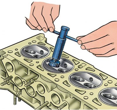
5. For the inlet valve seats, bring the width of the working chamfer to the values shown in Fig. Inlet valve seat profile, by first processing the inner chamfer with countersink A.94003 to obtain a size of ∅ 33, and then the 200 chamfer with countersink A.94101 to obtain a working chamfer with a width of 1.9–2 mm.