




Valve Mechanism Parts
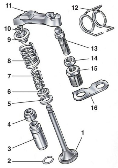
1 – valve; 2 – retaining ring; 3 – guide bushing; 4 – oil deflector cap; 5 – outer spring support washer; 6 – inner spring support washer; 7 – inner spring; 8 – outer spring; 9 – spring plate; 10 – crackers; 11 – valve drive lever; 12 – lever spring; 13 – adjustment bolt; 14 – adjusting bolt lock nut; 15 – adjusting bolt sleeve; 16 – lever spring locking plate
1. Install the cylinder head on the board A.60335.
2. Disconnect the outlet pipe of the cooling jacket and the pipe that drains the liquid to the heater. Disconnect the exhaust manifold and the intake pipe with the carburetor (the hot air intake is removed at the same time).
3. Remove the 11 valve levers, releasing them from the springs. Remove the lever springs.
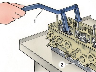
4. Install the A.60311/R tool as shown in the figure (1 – A.60311/B tool; 2 – mounting board). Compress the valve springs and release the crackers. Instead of the portable device A.60311/B, the stationary device 02.7823.9505 can also be used.
5. Remove the valve springs with the plates and support washers. Turn the cylinder head and remove the valves from the bottom.
6. Remove the oil seals from the guide bushings.
7. Remove the spark plugs using key 67.7812.9515. Assemble the cylinder head in the reverse order.
The original can be seen on the website [VAZBOOK.ru]