




Open large image in new tab »
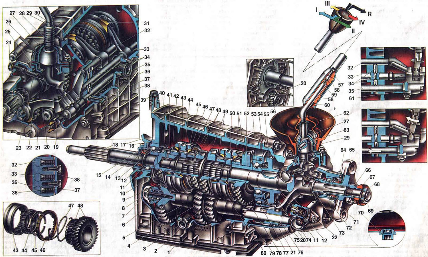
Fig. 15. Four-speed gearbox.
1. Bottom cover; 2. Filler and inspection hole plug; 3. Second gear gear of the intermediate shaft; 4. Third gear gear of the intermediate shaft; 5. Intermediate shaft; 6. Front intermediate shaft bearing; 7. Clamp washer bolt; 8. Intermediate shaft front bearing clamp washer; 9. Intermediate shaft constant mesh gear; 10. Primary shaft constant mesh gear; 11. Spring washer; 12. Retaining ring; 13. Rear bearing of the primary shaft; 14. Primary shaft seal; 15. Front gearbox cover; 16. Bearing mounting ring; 17. Clutch housing; 18. Gearbox drive shaft; 19. Reverse light switch; 20. Intermediate shaft reverse gear; 21. Reverse intermediate gear; 22. Reverse gear fork; 23. Gear shift lever return spring; 24. Bolt of the return spring; 25. Gear shift lever guide cup; 26. Ball joint of the lever; 27. Spherical washer; 28. Spring; 29. Gear shift lever; 30. Fork for engaging 1st and 2nd gears; 31. Fork for engaging III and IV gears; 32. Rod of the fork for engaging 1st and 2nd gears; 33. Fork rod for engaging III and IV gears; 34. Blocking crackers; 35. Reverse gear fork rod; 36. Ball piston rod lock; 37. Lock spring; 38. Retainer cover; 39. Sapun; 40. Needle bearing of the front end of the driven shaft; 41. Synchronizer spring thrust washer; 42. Synchronizer ring gear of the 4th gear; 43. Sliding clutch of synchronizer of III and IV gears; 44. Hub of the sliding clutch of the synchronizer of III and IV gears; 45. Synchronizer retaining ring; 46. Synchronizer locking ring; 47. Synchronizer spring; 48. Gear and ring gear of the synchronizer of the third gear; 49. Synchronizer pinion and ring gear of the 2nd gear; 50. Secondary shaft; 51. Gear and ring gear of the 1st gear synchronizer; 52. 1st gear bushing; 53. Secondary shaft intermediate bearing; 54. Intermediate bearing retaining plate; 55. Secondary shaft reverse gear; 56. Reverse gear intermediate shaft retaining ring; 57. Elastic cushion of the gearshift lever damper; 58. Rubber bushing of the damper; 59. Damper spacer sleeve; 60. Damper locking sleeve; 61. Rod spacer sleeve; 62. Inner gear shift lever boot; 63. Lever guide pin; 64. Secondary shaft rear bearing seal; 65. Flange of the flexible coupling of the cardan shaft; 66. Nut; 67. Centering ring seal; 68. Centering ring; 69. Retaining ring; 70. Secondary shaft rear bearing; 71. Drain plug; 72. Mud deflector; 73. Speedometer drive pinion; 74. Speedometer drive; 75. Rear cover of the gearbox; 76. Reverse intermediate gear shaft; 77. Intermediate shaft rear bearing; 78. Gear of the 1st gear of the intermediate shaft; 79. Gearbox housing; 80. Sliding clutch of synchronizer of 1st and 2nd gears.
1. Bottom cover; 2. Filler and inspection hole plug; 3. Second gear gear of the intermediate shaft; 4. Third gear gear of the intermediate shaft; 5. Intermediate shaft; 6. Front intermediate shaft bearing; 7. Clamp washer bolt; 8. Intermediate shaft front bearing clamp washer; 9. Intermediate shaft constant mesh gear; 10. Primary shaft constant mesh gear; 11. Spring washer; 12. Retaining ring; 13. Rear bearing of the primary shaft; 14. Primary shaft seal; 15. Front gearbox cover; 16. Bearing mounting ring; 17. Clutch housing; 18. Gearbox drive shaft; 19. Reverse light switch; 20. Intermediate shaft reverse gear; 21. Reverse intermediate gear; 22. Reverse gear fork; 23. Gear shift lever return spring; 24. Bolt of the return spring; 25. Gear shift lever guide cup; 26. Ball joint of the lever; 27. Spherical washer; 28. Spring; 29. Gear shift lever; 30. Fork for engaging 1st and 2nd gears; 31. Fork for engaging III and IV gears; 32. Rod of the fork for engaging 1st and 2nd gears; 33. Fork rod for engaging III and IV gears; 34. Blocking crackers; 35. Reverse gear fork rod; 36. Ball piston rod lock; 37. Lock spring; 38. Retainer cover; 39. Sapun; 40. Needle bearing of the front end of the driven shaft; 41. Synchronizer spring thrust washer; 42. Synchronizer ring gear of the 4th gear; 43. Sliding clutch of synchronizer of III and IV gears; 44. Hub of the sliding clutch of the synchronizer of III and IV gears; 45. Synchronizer retaining ring; 46. Synchronizer locking ring; 47. Synchronizer spring; 48. Gear and ring gear of the synchronizer of the third gear; 49. Synchronizer pinion and ring gear of the 2nd gear; 50. Secondary shaft; 51. Gear and ring gear of the 1st gear synchronizer; 52. 1st gear bushing; 53. Secondary shaft intermediate bearing; 54. Intermediate bearing retaining plate; 55. Secondary shaft reverse gear; 56. Reverse gear intermediate shaft retaining ring; 57. Elastic cushion of the gearshift lever damper; 58. Rubber bushing of the damper; 59. Damper spacer sleeve; 60. Damper locking sleeve; 61. Rod spacer sleeve; 62. Inner gear shift lever boot; 63. Lever guide pin; 64. Secondary shaft rear bearing seal; 65. Flange of the flexible coupling of the cardan shaft; 66. Nut; 67. Centering ring seal; 68. Centering ring; 69. Retaining ring; 70. Secondary shaft rear bearing; 71. Drain plug; 72. Mud deflector; 73. Speedometer drive pinion; 74. Speedometer drive; 75. Rear cover of the gearbox; 76. Reverse intermediate gear shaft; 77. Intermediate shaft rear bearing; 78. Gear of the 1st gear of the intermediate shaft; 79. Gearbox housing; 80. Sliding clutch of synchronizer of 1st and 2nd gears.
The gearbox is four-speed. All its parts are located in two basic parts: in the crankcase 79 and the rear cover 75. The primary shaft 18, the secondary shaft 50 assembled with gears and synchronizers and the intermediate shaft 5 are installed in the crankcase. The primary shaft rotates in two bearings, the front one is located at the end of the crankshaft, the rear bearing 13 is in the socket of the front wall of the crankcase. Its mounting ring is clamped between the clutch and gearbox housings. On the shaft, the bearing is clamped between the shaft flange and the spring washer 11, which is locked on the shaft by the retaining ring 12. With such fixation of the bearing in the socket and on the shaft, axial displacement of the shaft is excluded.
The primary shaft is manufactured together with the helical ring gear 10, which is in constant engagement with the gear 9 of the intermediate shaft. From the end of the shaft, a straight-toothed ring gear 42 of the 4th gear synchronizer is pressed onto the machined belt and then soldered with copper. In the same end of the shaft, a seat is machined for the needle bearing 40 of the secondary shaft. The driven clutch disk is located on the splines of the shaft.
The secondary shaft 50 is, as it were, an extension of the primary shaft. It rests on three bearings. The needle bearing 40 is located at the end of the primary shaft, the intermediate bearing 53 is in the rear wall of the crankcase, and the rear double-row bearing 70 is in the socket of the rear cover of the gearbox. The intermediate bearing is held from displacement in the socket by the mounting ring and the locking plate 54, which is fastened to the wall of the crankcase with screws. On the shaft, the bearing is clamped between the bushing 52 and the reverse gear 55 under the force of the spring washer 11, which is held on the shaft by the locking ring 12. The rear bearing 70 is clamped by the nut 66 between the speedometer drive gear 73 and the flange 65 of the elastic coupling. The nut is locked by a washer, which is bent onto the edge of the nut. At the outlet from the cover, the secondary shaft is sealed with a gland, the working edge of which is adjacent to the ground surface of flange 65. The gland is protected by a mud deflector 72. A rubber seal 67 is tightly seated on the cylindrical belt of the nut, then a centering ring 68 is pressed onto the end of the shaft and a locking ring 69 is installed. Gears 48 and 49 of the 3rd and 2nd gears rotate on the heat-treated journals of the secondary shaft. Gear 51 of the 1st gear rotates on a steel heat-treated bushing 52 clamped on the shaft between bearing 53 and the synchronizer hub. These gears have two rims each. Helical rims are in constant engagement with the same-name gears of the intermediate shaft, and clutches 43 and 80 of the synchronizers are connected to straight-tooth rims when the 1st, 2nd or 3rd gears are engaged. On two secondary shaft belts there are three deep grooves, into which the projections of the synchronizer clutch hubs enter. The synchronizer hub 44 of the III and IV gears is pressed against the shaft flange by a spring washer and is locked on the shaft by a ring. The other hub is clamped between the sleeve 52 and the shaft flange. It is held from axial displacement together with the intermediate bearing 53 and gear 55 by a spring washer 11 and a locking ring 12. The reverse gear 55 is connected to the shaft by a key.
The synchronizer is of the inertial type and ensures shock-free gear engagement. The design of both synchronizers is identical. The synchronizer of the third and fourth gears consists of a hub 44, a sliding clutch 43, two blocking rings 46, springs 47, locking rings 45 and synchronizer rims of the primary shaft and gear 48 of the third gear.
The intermediate shaft 5 is made in the form of a block of four gears. The shaft rotates in a double-row ball bearing 6 and a cylindrical roller bearing 77. The bearing is fastened to the shaft with a bolt 7 through a spring and flat washers. The roller bearing is clamped on the shaft between the shaft flange and the reverse gear 20. This gear is installed on the shaft splines and is held on them by a retaining ring.
The intermediate gear 21 of the reverse gear is located on the axis 76 on a metal-ceramic bushing. The axis is installed in the holes of the wall of the crankcase and the lug of the rear cover of the gearbox and is locked by the plate 54.
[The source is on the website VAZbook]
The gear shifting and switching is performed by means of a mechanical drive consisting of a lever 29, three rods with forks, locks and a locking device. The gear shift lever is made detachable to facilitate the removal and installation of the gearbox on the vehicle. The lever rod is connected to the lever itself through elastic damper bushings that absorb vibrations and provide a softer gear shifting. The gear shift lever is mounted in the rear cover 75. The guide cup 25 of the lever, the ball joint 26 and the flange of the sealing boot 62 are attached to the cover on three studs with nuts and spring washers. Sealing gaskets are installed between them. The lever 29 has a support ball that is pressed by the spring 28 to the surface of the ball joint. The same spring presses the spherical washer 27 from above to the ball joint. To prevent the lever hinge from turning in the ball joint, a pin 63 is pressed into the support ball, the end of which enters the hole in the support. The ball joint is protected by a rubber cover 62, and the place where the lever exits into the car interior is sealed from below with a cuff.
The synchronizer clutches and the intermediate reverse gear are moved by forks that are secured to the rods with bolts. Rod 33 of the fork for engaging III and IV gears is installed in the openings of the front and rear walls of the crankcase, and rods 32 and 35 in the openings of the rear wall and the crankcase lug. In the neutral and engaged positions, the rods are held by ball locks that are pressed against the rod seats by springs 37. The locks are closed by a common cover 38. To prevent the simultaneous engagement of two gears, the drive has a locking device consisting of three locking crackers 34. The two outer crackers of larger diameter are installed in the opening of the rear wall, and the middle one is in the opening of rod 33.