

Open large image in new tab »
Pic. 10. Carburetor model 21053-1107010.
1. Carburetor heating block; 2. Throttle valve of the first chamber; 3. Branch pipe for suction of crankcase gases; 4. Accelerator pump drive lever; 5. Accelerator pump drive cam; 6. Accelerator pump diaphragm; 7. Fuel jet economizer power modes; 8. Carburetor body; 9. Economizer diaphragm power modes; 10. Electromagnetic shut-off valve; 11. Fuel jet idling; 12. Carburetor cover; 13. Fuel supply pipe; 14. The main air jet of the first chamber; 15. Air damper; 16. Accelerator pump nozzles with fuel supply valve; 17. Diaphragm of the starting device; 18. Trigger adjustment screw; 19. Adjusting screw for the amount of idle mixture; 20. Second chamber lock lever; 21. Vacuum supply pipe to the vacuum regulator of the ignition distributor; 22. Adjusting screw for the quality of the idle mixture; 23. Throttle actuator lever; 24. Adjusting screw for slightly opening the throttle valve of the first chamber; 25. Choke control lever; 26. The rod of the starting device; 27. Electric wire of the economizer limit switch for forced idling; 28. Choke lever; 29. The main air jet of the second chamber; 30. Emulsion tube of the second chamber; 31. Atomizer of the main dosing system of the second chamber; 32. Fuel filter; 33. Float chamber needle valve; 34. Throttle valve of the second chamber; 35. Throttle lever of the second chamber; 36. The main fuel jet of the second chamber; 37. Throttle actuator lever of the second chamber; 38. Float.
1. Carburetor heating block; 2. Throttle valve of the first chamber; 3. Branch pipe for suction of crankcase gases; 4. Accelerator pump drive lever; 5. Accelerator pump drive cam; 6. Accelerator pump diaphragm; 7. Fuel jet economizer power modes; 8. Carburetor body; 9. Economizer diaphragm power modes; 10. Electromagnetic shut-off valve; 11. Fuel jet idling; 12. Carburetor cover; 13. Fuel supply pipe; 14. The main air jet of the first chamber; 15. Air damper; 16. Accelerator pump nozzles with fuel supply valve; 17. Diaphragm of the starting device; 18. Trigger adjustment screw; 19. Adjusting screw for the amount of idle mixture; 20. Second chamber lock lever; 21. Vacuum supply pipe to the vacuum regulator of the ignition distributor; 22. Adjusting screw for the quality of the idle mixture; 23. Throttle actuator lever; 24. Adjusting screw for slightly opening the throttle valve of the first chamber; 25. Choke control lever; 26. The rod of the starting device; 27. Electric wire of the economizer limit switch for forced idling; 28. Choke lever; 29. The main air jet of the second chamber; 30. Emulsion tube of the second chamber; 31. Atomizer of the main dosing system of the second chamber; 32. Fuel filter; 33. Float chamber needle valve; 34. Throttle valve of the second chamber; 35. Throttle lever of the second chamber; 36. The main fuel jet of the second chamber; 37. Throttle actuator lever of the second chamber; 38. Float.
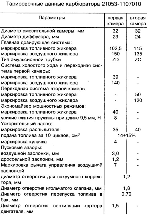
On VAZ-21065 cars, a carburetor of model 21053-1107010 is installed. Calibration data for the carburetor are shown in the table.
The carburetor has a balanced float chamber, a crankcase exhaust system for the throttle valve, and a blocking of the second chamber. The carburetor has two main metering systems of the first and second chambers, an idle system of the first chamber with a transition system, a transition system of the second chamber, a forced idle economizer, a power mode economizer, a mechanically driven diaphragm accelerator pump and a diaphragm starter.
The carburetor consists of two body parts: body 8 and cover 12 of the carburetor. In the inlet neck of the first chamber, an air damper 15 of the starting device is installed. A lever 28 with two pins is rigidly mounted on the axis of the air damper, one of which is fitted with a return spring. The second pin enters the shaped groove of the lever 25 of the air damper control. The adjusting screw 24 for slightly opening the throttle valve of the first chamber and the pin of the lever 20 for blocking the second chamber rest on the outer edge of the lever 25.
In the cover 12 of the carburetor, a needle shut-off valve 33 for the fuel supply, a float 38, a fuel filter 32, a pipe 13 for supplying fuel to the float chamber are installed. To the tide of the cover 12, the cover of the starting device with the diaphragm 17, assembled with the stem 26, is attached. The electromagnetic shut-off valve 10 with the idle fuel jet is wrapped in the cover.
Large diffusers are cast in the carburetor body 8 and small, easily removable diffusers are installed, cast integrally with the sprayers of the main dosing systems. In housing 8, sprayers 16 of an accelerator pump with a ball valve, main air jets 14 and 29 with emulsion tubes 30 in emulsion wells, an intake pipe of the transition system with a fuel jet are installed. The main fuel jets 36 are wrapped in the emulsion wells. In the tides of the carburetor body, an adjusting screw for the completeness of closing the throttle valve 34 of the second chamber, as well as an adjusting screw 19 for the amount of idle mixture with an electric drive 27 of the economizer limit switch for forced idling, are installed. An adjusting screw 22 for the quality of the idle mixture is wrapped in the housing.
To the tide of the housing 8, which forms the working cavity of the accelerator pump, the cover of the accelerator pump with the lever 4 of the drive assembly with the diaphragm 6 of the pump is attached with four screws. The cover of the power mode economizer with a working diaphragm 9 is also fastened to the body with screws. A spring acts on the diaphragm. A fuel jet 7 and an economizer valve for power modes are installed in the carburetor body under the diaphragm 9.
In the lower part of the body 8, throttle valves 2 and 34 are installed on the axes. On the axis of the throttle valve of the first chamber, the following are installed: throttle actuator lever 23 with an adjusting screw 24 for slightly opening the damper and with a lever 20 for blocking the second chamber; the lever 37 of the throttle actuator of the second chamber; return spring and cam 5 of the accelerator pump. Throttle lever 35 is mounted on the throttle valve axis of the second chamber.
Blocking of the second chamber does not allow the opening of the throttle valve of the second chamber in any mode of engine operation, if the air damper is not fully open. The blocking excludes the operation of the second mixing chamber when the engine is cold.
Note.
1. The conditional consumption of the fuel jet is determined by the reference jet using a special method. It is not subject to control during operation.
2. The marking of the jets is determined by the flow rate, which is measured using micrometers. Adjustment of micrometers is carried out according to reference jets.