




Contents: Gearbox housing ↓ Primary shaft ↓ Secondary shaft ↓ Synchronizer ↓ Intermediate gear ↓ Differential ↓
The gearbox converts the torque transmitted from the engine in magnitude and direction. This is necessary to ensure optimal speed and cross-country ability of the car, as well as for the most economical operation of the engine and the movement of the car in reverse. In addition, the gearbox disconnects the engine from the transmission when the car is stopped and when it moves by inertia with the engine running.
Due to the small number of gears, the gearbox is compact and simple in design. The selected gear ratios provide intensive acceleration, high average speed and economical engine operation. Helical gears of constant engagement and synchronizers on all forward gears ensure silent operation of the gearbox and its durability.
Depending on the vehicle configuration, a four- or five-speed gearbox may be installed, combined with the main gear, the gear ratio of which may have several values: 3.94 for the VAZ-2108; 4.13 — for VAZ-21081; 3.7 or 3.94 for VAZ-21083 or VAZ-2109 and its modifications. VAZ-21081 cars are equipped with a four-speed gearbox, and other models and their modifications can be equipped with either gearbox.
The four-speed gearbox consists of a primary 23 (figure 59) and secondary 33 shafts with gears and synchronizers, an axle with an intermediate reverse gear, a differential and a gear shift drive. The shafts and gears of the gearbox and main gear, as well as the differential, are located in an aluminum housing 1.
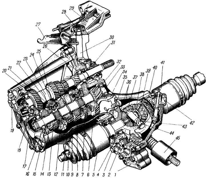
Figure 59. Gearbox assembly:
1 - box housing; 2 - filler and control hole plug; 3 - drain plug; 4 - adjusting ring; 5 - left front wheel drive; 6 - driven gear of the 1st gear of the secondary shaft; 7 - synchronizer clutch for 1st, 2nd gears and reverse; 8 - driven gear of the 2nd gear of the secondary shaft; 9 - retaining ring; 10 - thrust half ring; 11 - driven gear of the 3rd gear of the secondary shaft; 12 - hub of synchronizer clutch of III and IV gears; 13 - driven gear of the IV gear of the secondary shaft; 14 - secondary shaft gear needle bearing; 15 - thrust washer of the fourth gear; 16 - secondary shaft ball bearing; 17 - rear cover of the gearbox; 18 - primary shaft ball bearing; 19 - breather; 20 - locking ring of synchronizer of III and IV gears; 21 - sliding clutch of synchronizer III and IV gears; 22 - retainer cracker; 23 - primary shaft; 24 - retainer ball; 25 - fork of sliding clutch of synchronizer of III and IV gears; 26 - primary shaft cylindrical bearing; 27 - clutch release fork lever; 28 - Clutch release fork bushing; 29 - clutch housing; 30 - clutch release fork; 31 - clutch release fork bearing; 32 - secondary shaft roller bearing; 33 - secondary shaft; 34 - driven gear of the main transmission; 35 differential tapered roller bearing; 36 - differential box; 37 - satellite; 38 - axle gear retaining ring; 39 - axle gear; 40 - speedometer drive pinion; 41 - Right front wheel drive; 42 - speedometer drive; 43 - satellite axle. 44 - satellite axle retaining ring; 45 - protective cover of the gear shift drive hinge.
Gearbox housing
The gearbox housing is connected with studs to the clutch housing 29 during gearbox assembly and together they form a single unit. On the other side, the rear cover 17 is attached to the gearbox housing, into which the breather 19 is pressed, communicating the cavity of the housing with the atmosphere. This eliminates the increase in pressure in the housing and oil leakage through the seals. The housing contains seats for the bearings of the primary and secondary shafts, as well as for the locking pins of the gearshift rods. The locking pins are closed by a common cover 8 (see figure 62), and the reverse lock is closed by plug 12. There is a hole for filling the gearbox with oil, which is closed by plug 2 (see figure 59), and for draining the oil there is a hole closed by plug 3. The oil level should reach the lower edge of the filler hole.
Primary shaft
Primary shaft 23 rotates in two bearings. Cylindrical roller bearing 26 is installed in the clutch housing socket, ball bearing — in the gearbox housing socket. The front end of the shaft at the outlet from the housing is sealed with an oil seal, which is closed by the flange of the guide sleeve of the clutch release bearing coupling. This flange is fastened to the clutch housing with three bolts. The sleeve of the clutch release bearing 31 is located on the sleeve. The rear bearing 18 is fixed on the shaft with a nut and is held from axial displacement in the housing socket by a mounting ring, which is pressed by cover 17 to the gearbox housing. The nut is fixed by calking its belt into the shaft groove.
The primary shaft is made in the form of a block of leading gears of I, II, III, IV gears and reverse. The driven clutch disc is located on the splined end of the shaft.
Secondary shaft
The secondary shaft 33 is made as one piece with the main gear pinion. The front end of the shaft rests on the cylindrical roller bearing 32, and the rear end rests on the ball bearing 16. The front bearing is located in the clutch housing socket, into which a rubber plug is pressed for sealing. The rear bearing is fastened to the shaft with a nut, which is fixed in the same way as on the primary shaft. The secondary shaft is held together with the rear bearing from axial displacement by its mounting ring.
On the secondary shaft, driven gears of the 1st, 2nd, 3rd and 4th gears and two synchronizers are mounted on needle bearings with plastic separators. The needle bearings are of the "bracelet" type, which facilitates the installation of gears on the shaft. Mounting gears on needle bearings reduces friction losses and increases the efficiency of the gearbox. Gear 6 of the first gear is clamped between the thrust washer and the locking ring of the hub of the synchronizer of the 1st, 2nd gears and reverse, gear 8 of the second gear is between the second locking ring of the same hub of the synchronizer and the thrust half rings 10 of the secondary shaft. The half rings are fixed on the shaft with a ball and a locking ring 9, put on the half rings. Gears of the 3rd and 4th gears are similarly mounted on the shaft. Only the needle bearing of the fourth gear pinion 13 is placed on the sleeve and between the bearing and the foot there is a spacer ring, and between the sleeve and the ball bearing there is a thrust washer 15.
Synchronizer
The synchronizer consists of a hub 5 (figure 60), rigidly connected to the secondary shaft by means of splines, sliding clutch 2, two blocking rings 1, three crackers 4 with locks 3 and springs, as well as toothed rims of synchronizers. Sliding clutch 7 (see figure 59) the synchronizer of the first and second gears has an outer ring for engaging the reverse gear.
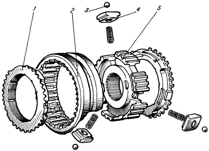
Figure 60. Synchronizer parts:
1 - blocking ring; 2 - sliding synchronizer clutch; 3 - retainer ball; 4 - retainer cracker; 5 - synchronizer clutch hub.
The hub of the synchronizer of the first and second gears is mounted on the splines of the secondary shaft and is fixed on the shaft from axial displacement by two retaining rings. The hub has six longitudinal grooves, three of which have sockets for the retainer springs. Crackers 4 are installed in these grooves (see figure 60) with locking balls. Springs press the locking pins to the annular grooves of the coupling. On both sides of the hub there are bronze locking rings I with toothed rims, the pitch of which is equal to the pitch of the internal teeth of the sliding coupling and the toothed rims of the gears of the first and second gears. The locking rings have six projections each, which enter the grooves of the hub, while three short projections enter the grooves in which the locking pins are located, and longer and wider ones enter other grooves. These projections are installed in the grooves with a lateral clearance equal to half the thickness of the coupling (hub) tooth, and limit the angle of rotation of the locking ring relative to the hub. Thus, the hub rotates together with the locking rings. With their conical surface, the locking rings contact the conical belts of the gear of the first or second gear at the moment of gear engagement. To break the oil film at the point of contact and increase friction forces, particularly fine threads and longitudinal grooves are cut on the conical surface of the ring.
The sliding clutch with its inner rim is mounted on the outer toothed rim of the hub and can move along the hub. For this purpose, the gear shift fork enters the annular groove of the clutch. The ends of the clutch teeth are beveled at the same angle as the teeth of the locking rings and synchronizer rims.
Intermediate gear
Intermediate gear 5 (figure 61) reverse gear is straight-toothed. A bushing is pressed into its hole, through which the axis 4 passes. It is installed in the holes of the clutch housing and gearbox. The fork 6 for engaging the reverse gear enters the groove of the gear.
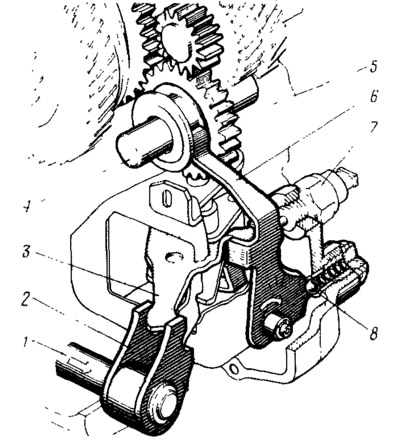
Figure 61. Reverse intermediate gear:
1 - gear selection current; 2 - gear selection rod lever; 3 - three-arm gear selector lever; 4 - reverse intermediate gear axis; 5 - intermediate reverse gear; 6 - reverse gear fork; 7 - Reversing light switch; 8 - reverse fork lock.
Differential
The differential is a dual-satellite one. Its box is 36 (see figure 59) rotates in two tapered bearings 35, the preload in which is adjusted by selecting the thickness of ring 4. The driven gear 34 of the main transmission is attached to the flange of the differential box, and the plastic gear 40 of the speedometer drive 42 is pressed onto the differential box. Gear 34 is in constant engagement with the driving gear of the main transmission of the secondary shaft.
Satellites 37 and half-axle gears 39 have spherical support surfaces. The use of a solid sphere in the differential box, coupled with gears and satellites, made it possible to eliminate the support washers of the half-axle gears.
The satellites are located on the axle 43, which is held in the holes of the differential box by retaining rings 44. Grooves for retaining grease are made on the landing journals of the axle. The holes of the half-axle gears have internal splines, into which the splined tails of the housings of the internal joints of the front wheel drives enter.