




Open large image in new tab »
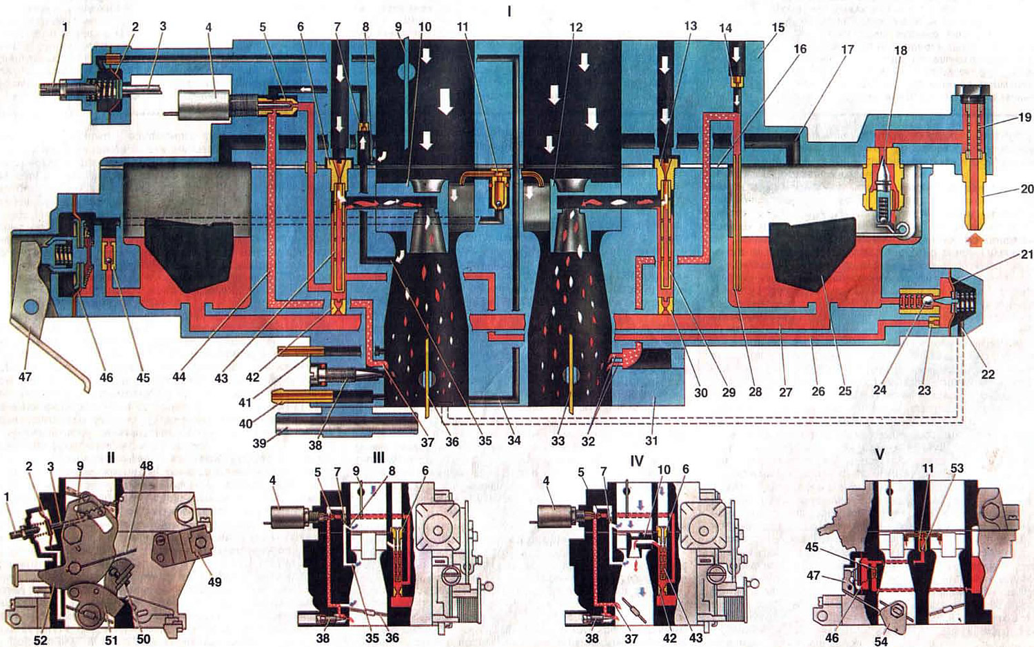
Fig. 11. Operation of carburetor 21053-1107010.
1. Starter adjustment screw; 2. Diaphragm of the starting device; 3. Starter rod; 4. Solenoid shut-off valve; 5. Idle fuel jet; 6. Main air jet of the first chamber; 7. Idle air jet; 8. Idle flow channel; 9. Air damper; 10. Sprayer of the main dosing system of the first chamber; 11. Accelerator pump nozzles; 12. Sprayer of the main dosing system of the second chamber; 13. Main air jet of the second chamber; 14. Air jet of the transition system of the second chamber; 15. Carburetor cover; 16. Gasket; 17. Float chamber balancing hole; 18. Needle valve; 19. Fuel filter; 20. Fuel supply pipe; 21. Diaphragm of the power mode economizer; 22. Air duct of the power mode economizer; 23. Fuel jet of the power mode economizer; 24. Ball valve of power mode economizer; 25. Float; 26. Fuel channel of the power mode economizer; 27. Fuel channel of the main fuel jets; 28. Fuel jet of the transition system of the 2nd chamber with a tube; 29. Emulsion tube of the second chamber; 30. Main fuel jet of the second chamber; 31. Carburetor body; 32. Output openings of the transition system of the second chamber; 33. Second chamber throttle valve; 34. Air channel of the starting device; 35. Idle air duct opening; 36. Throttle valve of the first chamber; 37. Slit of the transition system of the first chamber; 38. Idle mixture quality adjusting screw; 39. Carburetor heating unit; 40. Crankcase gas suction pipe; 41. Pipe for supplying vacuum to the vacuum ignition advance regulator; 42. Main fuel jet of the first chamber; 43. Emulsion tube of the first chamber; 44. Idle emulsion channel; 45. Accelerator pump ball valve; 46. Accelerator pump diaphragm; 47. Accelerator pump drive lever; 48. Air damper drive handle rod; 49. Bracket for fastening the air damper drive rod casing; 50. Adjusting screw for opening the throttle valve of the first chamber; 51. Throttle actuator lever; 52. Air damper control lever; 53. Ball valve for fuel supply to the accelerator pump; 54. Accelerator pump drive cam; I. Carburetor operation at maximum engine power; II. Operation of the starting device; III. Operation of the carburetor at engine idle speed; IV. Operation of the carburetor when switching to medium loads; V. Operation of the accelerator pump.
1. Starter adjustment screw; 2. Diaphragm of the starting device; 3. Starter rod; 4. Solenoid shut-off valve; 5. Idle fuel jet; 6. Main air jet of the first chamber; 7. Idle air jet; 8. Idle flow channel; 9. Air damper; 10. Sprayer of the main dosing system of the first chamber; 11. Accelerator pump nozzles; 12. Sprayer of the main dosing system of the second chamber; 13. Main air jet of the second chamber; 14. Air jet of the transition system of the second chamber; 15. Carburetor cover; 16. Gasket; 17. Float chamber balancing hole; 18. Needle valve; 19. Fuel filter; 20. Fuel supply pipe; 21. Diaphragm of the power mode economizer; 22. Air duct of the power mode economizer; 23. Fuel jet of the power mode economizer; 24. Ball valve of power mode economizer; 25. Float; 26. Fuel channel of the power mode economizer; 27. Fuel channel of the main fuel jets; 28. Fuel jet of the transition system of the 2nd chamber with a tube; 29. Emulsion tube of the second chamber; 30. Main fuel jet of the second chamber; 31. Carburetor body; 32. Output openings of the transition system of the second chamber; 33. Second chamber throttle valve; 34. Air channel of the starting device; 35. Idle air duct opening; 36. Throttle valve of the first chamber; 37. Slit of the transition system of the first chamber; 38. Idle mixture quality adjusting screw; 39. Carburetor heating unit; 40. Crankcase gas suction pipe; 41. Pipe for supplying vacuum to the vacuum ignition advance regulator; 42. Main fuel jet of the first chamber; 43. Emulsion tube of the first chamber; 44. Idle emulsion channel; 45. Accelerator pump ball valve; 46. Accelerator pump diaphragm; 47. Accelerator pump drive lever; 48. Air damper drive handle rod; 49. Bracket for fastening the air damper drive rod casing; 50. Adjusting screw for opening the throttle valve of the first chamber; 51. Throttle actuator lever; 52. Air damper control lever; 53. Ball valve for fuel supply to the accelerator pump; 54. Accelerator pump drive cam; I. Carburetor operation at maximum engine power; II. Operation of the starting device; III. Operation of the carburetor at engine idle speed; IV. Operation of the carburetor when switching to medium loads; V. Operation of the accelerator pump.
Main dosing system is fed from the float chamber, into which fuel enters through the needle valve 18. Through the main fuel jets 42 and 30, the fuel enters the emulsion wells. With sufficient vacuum in the sprayers of the main metering systems, the fuel mixes in the emulsion wells with air entering through the main air jets 6 and 13, and is sucked into the diffusers of the mixing chambers in the form of an emulsion. In the throttling mode, only the main metering system of the first chamber operates. The second begins to open and operate when the throttle valve of the first chamber opens more than two-thirds.
Idle system provides the required composition of the combustible mixture at idle. In this case, throttle valves 36 and 33 are closed. Fuel from the emulsion well of the main metering system rises along the fuel channel, passes fuel jet 5, mixes with air from air jet 7 and the flow channel and then enters under the mixture quality screw 38 into the throttle space.
First chamber transition system provides a smooth transition of the engine operation from idle to throttle modes. At the moment of opening of the throttle valve of the first chamber, the gap 37 of the transition system falls under vacuum. Emulsion will also flow from it, providing a smooth transition.
Second chamber transition system ensures a smooth transition of engine operation at the moment of the beginning of the opening of the throttle valve of the second chamber. At this moment, the holes 32 fall under vacuum; fuel from the float chamber rises up the tube through jet 28, air is mixed in from air jet 14 and the emulsion enters through the emulsion channel through the outlet openings under the throttle valve.
Power mode economizer prevents a change in the degree of enrichment of the mixture due to the pulsation of the vacuum under the throttle valve, especially when the crankshaft speed decreases, when the pulsation increases and the vacuum decreases. The ball valve 24 of the economizer is closed while the diaphragm 21 is held by the vacuum under the throttle valve. When the throttle valve 36 is significantly opened, the vacuum decreases somewhat, and the diaphragm spring opens the valve. Fuel passes through the valve, the jet 23 of the economizer, is added to the fuel passing through the main fuel jet 42, and equalizes the enrichment of the mixture.
Accelerator pump - diaphragm type, with a drive from a cam on the axis of the throttle valve of the first chamber. When the throttle valve is opened sharply, the cam presses the lever 47 and through the spring in the pusher acts on the diaphragm 46, overcoming the resistance of the return spring. The diaphragm supplies fuel through the ball supply valve and injects it through the sprayers 11 into the mixing chambers. During the return stroke of the diaphragm, under the action of the return spring, fuel is sucked from the float chamber through the check ball valve 45 into the working cavity of the accelerator pump.
Cam 54 has a special profile that provides double injection. Moreover, the second injection coincides with the beginning of the opening of the throttle valve of the second chamber.
Starting device ensures the preparation of a rich combustible mixture when starting a cold engine. When turning the air damper control lever 52 by the rod 48 counterclockwise, the outer edge of the lever 52 by the adjusting screw 50 slightly opens the throttle valve 36 of the first chamber. At the same time, the expanding groove of the lever 52 releases the pin of the air damper lever, and it will be held completely closed due to the return spring. The axis of the air damper is offset, therefore the air damper after starting the engine can be slightly opened by the air flow, stretching the spring, which ensures the leaner mixture.
The vacuum from the throttle space, acting on the diaphragm 2, can slightly open the air damper by means of the rod 3. The adjusting screw 1 allows you to regulate the amount of damper opening.
Forced idle economizer disables the idle system at forced idle (braking the car with the engine, driving downhill, changing gears), which eliminates carbon monoxide emissions into the atmosphere.
The economizer includes a limit switch mounted on the adjusting screw 19 (see fig. 10) the amount of idle mixture, electromagnetic shut-off valve 10, electronic control unit and electrical wires connecting the instruments.
At forced idle, if the crankshaft speed begins to increase, then the voltage on the winding of the electromagnetic valve 4 (see fig. 11) is supplied by the electronic control unit until the shaft speed exceeds 2100 rpm, although the limit switch is closed to ground. At a higher speed, the electronic control unit turns off the power to the electromagnetic shut-off valve, as a result of which the fuel supply to the idle system is stopped.
When the engine crankshaft speed decreases at forced idle speed to 1900 rpm, the electronic control unit again begins to supply power to the valve winding, and it opens the fuel supply through the idle jet, although the limit switch is closed to ground.