




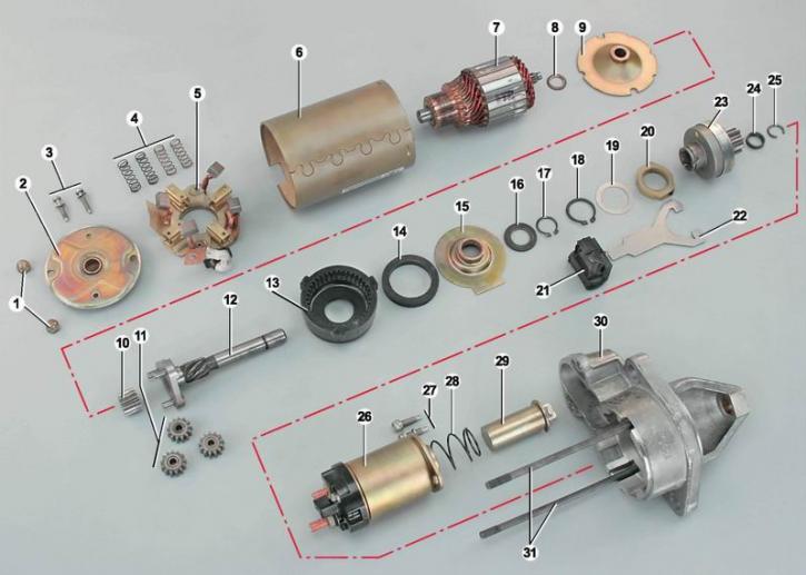
Starter details: 1 - rear cover mounting nuts; 2 - back cover; 3 - brush assembly mounting screws; 4 - brush springs; 5 - brush unit; 6 - stator (with magnets); 7 - anchor; 8 - thrust washer; 9 - armature shaft support; 10 - central gear of the reducer; 11 - planetary (satellite) gear reducer gears; 12 - drive shaft; 13 - external gear reducer with internal teeth; 14 - sealing ring; 15 - drive shaft support; 16 - thrust washer; 17 - Drive shaft retaining ring; 18 - Retaining ring of the drive lever coupling; 19 - washer; 20 - drive lever coupling; 21 - drive lever support; 22 - drive lever; 23 - drive; 24 - drive travel limiting ring; 25 Locking ring of the limiter; 26 - starter traction relay; 27 - traction relay mounting screws; 28 - return spring; 29 - traction relay core; 30 - front cover; 31 - tie rods
The engine anchor shaft and the drive shaft rotate in bronze-graphite bushings, which are installed in the rear and front covers of the starter, in the anchor shaft support and in the drive shaft support. The anchor shaft transmits rotation to the drive shaft through a planetary gearbox. The planetary gears of the gearbox rotate on needle bearings.
The starter drive consists of a pinion and an overrunning clutch. The drive can move along the spiral splines of the drive shaft.
The traction relay is designed for remote switching of the large current consumed by the starter when starting the engine, as well as mechanical connection of the starter drive with the toothed ring of the engine flywheel. The relay coil has two windings, a pull-in and a holding one.
When the ignition key is turned to the "starter" position, voltage is supplied to the control terminal of the traction relay "50", and from it to both relay windings from the storage battery. Under the influence of the magnetic field, the metal core of the traction relay, overcoming the force of the return spring, is drawn into the coil. In doing so, it sets the starter drive lever in motion. The drive lever with its horseshoe-shaped fork extends the starter drive, engaging the drive pinion with the toothed ring of the engine flywheel. At the same time, the copper contact plate located in the plastic cover of the traction relay closes the contact bolts. Current begins to flow through the starter anchor windings, and the anchor rotates, starting the engine.
The negative terminal of the relay pull-in winding is connected to the "ground" through the starter anchor windings (see diagram). After the contact bolts are closed, the current stops flowing through this winding and the traction relay core is held by only one winding. This allows for a reduction in the heating of the relay windings and a reduction in power consumption when the engine is started.
The overrunning roller clutch of the drive transmits rotation only in one direction - from the starter to the flywheel. After starting the engine, when the crankshaft speed increases sharply, the clutch protects the starter from destruction.
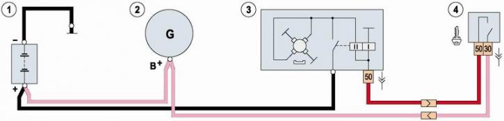
Starter electrical connection diagram: 1 - battery; 2 - generator; 3 - starter; 4 - ignition switch (lock).
Note: On cars of recent years of production, the starter circuit (between the traction relay and the ignition switch) an additional relay is installed.
After the driver releases the ignition key, the control voltage stops flowing to the traction relay output. The electromagnetic field holding the anchor disappears. The drive lever, under the influence of the spring, moves the starter drive back and removes the drive pinion from engagement with the flywheel crown. At the same time, the power contacts that supply current to the starter motor windings open.
Warning! The starter is the most powerful consumer of electrical energy in the car. When starting the engine, the current consumed by the starter can reach more than 400 A. Therefore, all electrical connections between the battery and the starter must have good and reliable contact.
Advice: Do not engage the starter for more than 15 seconds. Allow 20-30 seconds between attempts to start the engine. If the engine does not start after three attempts, you need to find out what the reason is (see "Diagnostics of car malfunctions and methods of their elimination"), and eliminate it.
The article is copied from the website [VAZbook.ru]