
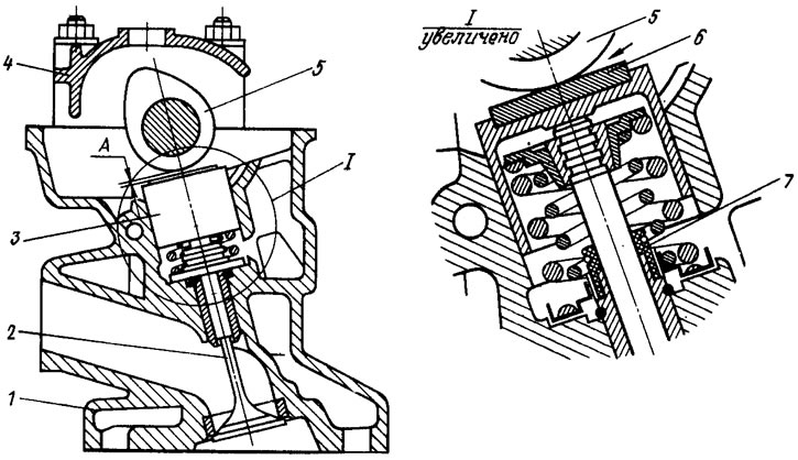
Pic. 5. Valve mechanism
The valves are actuated directly by the camshaft cams through cylindrical tappets 3 without intermediate levers. There is a washer 6 in the pusher seat, by selecting which the gap A in the gas distribution mechanism is adjusted.
Cylinder head
Cast aluminum with a wedge-shaped combustion chamber and press-fit cast iron seats and valve guides. The upper part of the bushings is sealed with metal-rubber oil deflector caps 7. There are spiral grooves in the holes of the guide bushings to improve lubrication. The inlet valve bushings are grooved up to half the length of the hole, and the exhaust valve bushings are cut along the entire length of the hole.
In the upper part of the cylinder head there are five bearings for the camshaft journals. The supports are detachable. The upper half is in bearing housings 4 (front and rear), and the lower one in the cylinder head. The bearing holes are machined complete with bearing housings, so they are not interchangeable and the cylinder head can only be replaced complete with bearing housings.
Camshaft
Cast iron, cast, 5-support. On the back of the shaft there is an eccentric for driving the fuel pump. The working surfaces of the cams, the eccentric and the surface under the stuffing box are bleached to increase wear resistance.
Camshaft drive
Carried out by an elastic toothed belt 6 (pic. 6) from the toothed pulley 1 of the crankshaft. The same belt drives the pulley 2 of the coolant pump. Roller 3 serves to tension the belt. It rotates on an eccentric axle 7 attached to the cylinder head. By turning the axle relative to the fastening stud, you can change the belt tension.
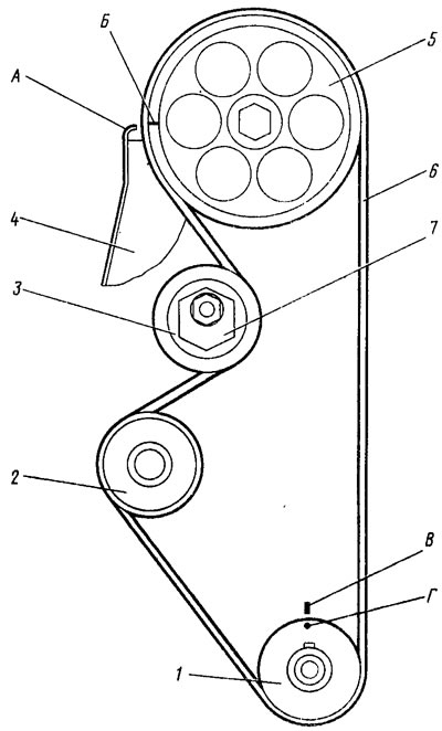
Pic. 6. Camshaft drive
To check the correct relative position of the drive pulleys, there are alignment marks: B on the camshaft pulley 5 and the corresponding protrusion A on the back cover 4 of the belt; G on pulley 1 of the crankshaft and the corresponding mark B on the oil pump cover.