English Русский
Български
Беларускі
Український
Српски
Hrvatski
Română
Polski
Slovenský
Magyar
| Articles | Contacts | Sitemap |   
Repair and maintenance Lada Repair and maintenance Mazda Repair and maintenance Mitsubishi Repair and maintenance Toyota Repair and maintenance Land Rover Repair and maintenance Hyundai Repair and maintenance Nissan
VAZbook.ru


Main     1111   2101   2105   2106   2107   2109   2110   2115   2121  
VAZ-2108 (1984-2003) VAZ-2109 (1984-1997) VAZ-21099 (1990-2004)
  • Main
  • «Sputnik»
  • VAZ-21099
  • Electrical equipment
  • Equipment and devices
  • Instrument panel (low)

Instrument panel (low) (VAZ-21099)

            0

Disconnect the wire from the "-" terminal of the storage battery. Set the wheels to the straight-ahead position. Disconnect the rod from the carburetor air damper drive lever and the speedometer drive cable from the gearbox.

Disconnect the wire from the «-» terminal of the storage battery. Set the wheels to the…


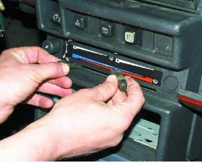
1. Remove the three heater control knobs.
1. Remove the three heater control knobs.


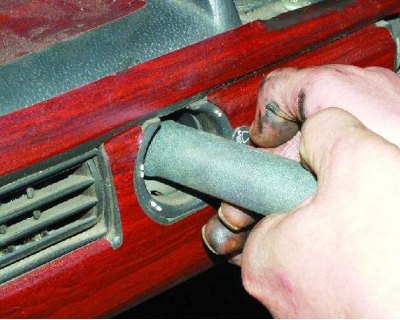
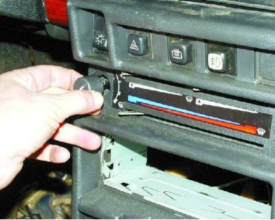
2. Remove the heater fan switch handle by pulling it towards you.

2. Remove the heater fan switch handle by pulling it towards you.


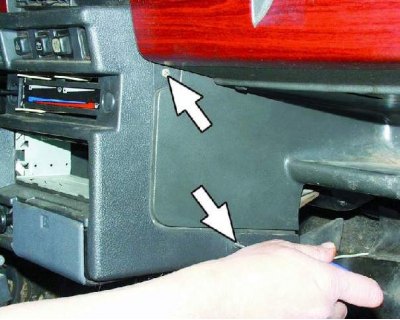
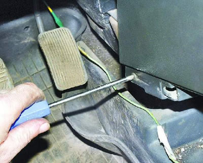
3. Remove two screws securing the instrument panel console trim on both sides of the console.


3. Remove two screws securing the instrument panel console trim on both sides of the console.


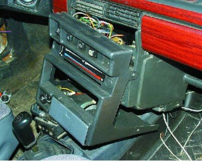
4. Slide the overlay towards you.

4. Slide the overlay towards you.


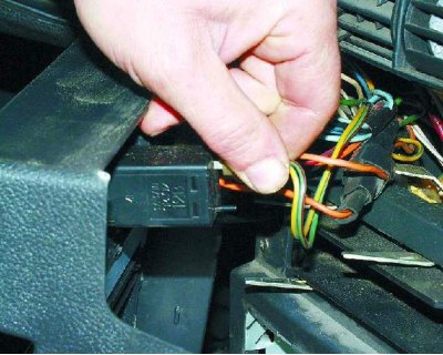
5. Disconnect the wiring harness from the rear fog light switch.
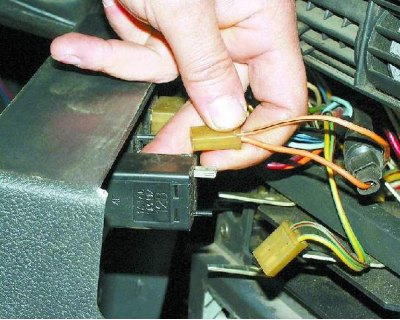
5. Disconnect the wiring harness from the rear fog light switch.


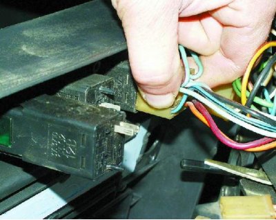
6. Disconnect the two connectors with wires and one wire from the rear window defroster switch.

6. Disconnect the two connectors with wires and one wire from the rear window defroster switch.


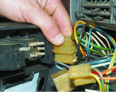
7. Disconnect the wiring harness from the hazard warning switch.


7. Disconnect the wiring harness from the hazard warning switch.


8. Remove the wiring harness from the exterior lighting switch.

8. Remove the wiring harness from the exterior lighting switch.


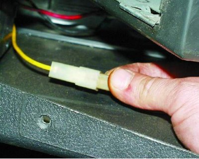
9. Disconnect the connector with the cigarette lighter backlight wires.

9. Disconnect the connector with the cigarette lighter backlight wires.


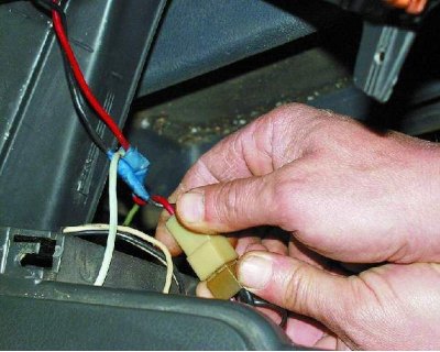
10. Disconnect the cigarette lighter wiring harness and remove the console trim.

10. Disconnect the cigarette lighter wiring harness and remove the console trim.


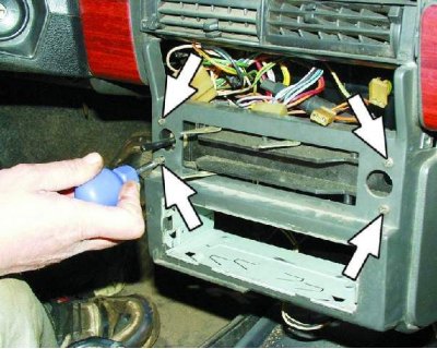
11. Remove the four screws securing the heater control panel.
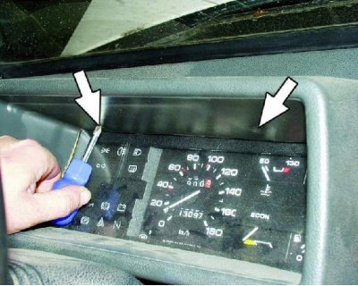
11. Remove the four screws securing the heater control panel.


12. Remove the two screws securing the instrument cluster visor.
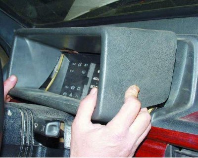
12. Remove the two screws securing the instrument cluster visor.


13. Remove the instrument cluster visor.
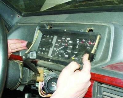
13. Remove the instrument cluster visor.


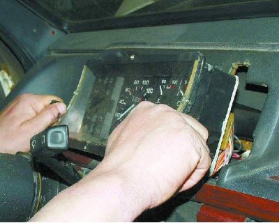
14. Compress the spring clips...

14. Compress the spring clips...


15....and remove the instrument cluster housing from the panel.
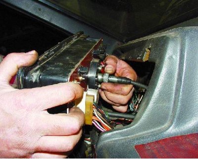
15....and remove the instrument cluster housing from the panel.


16. Loosen the mounting nut and disconnect the cable from the speedometer.
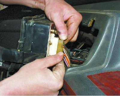
16. Loosen the mounting nut and disconnect the cable from the speedometer.


17. Disconnect the white wiring harness from the instrument cluster.

17. Disconnect the white wiring harness from the instrument cluster.


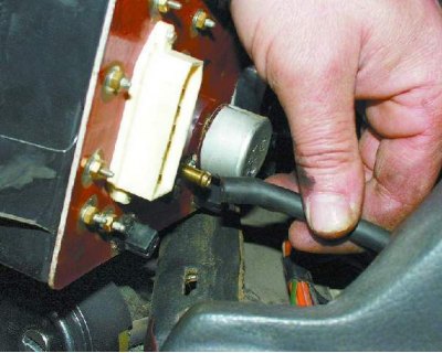
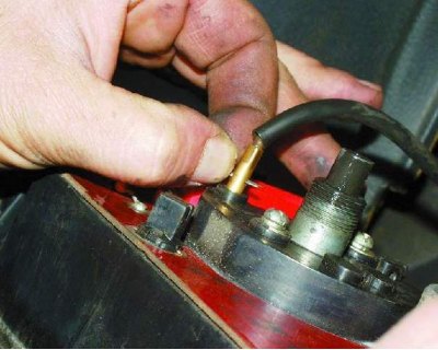
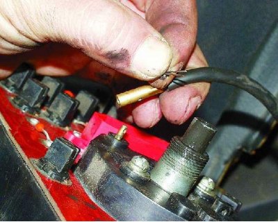
18. Remove the hose from the fuel economy meter fitting.

18. Remove the hose from the fuel economy meter fitting.


19. Remove the cotter pin.

19. Remove the cotter pin.


20. Disconnect the trip meter reset cable from the speedometer.
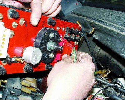
20. Disconnect the trip meter reset cable from the speedometer.


21. Disconnect the red connector from the instrument cluster.

21. Disconnect the red connector from the instrument cluster.


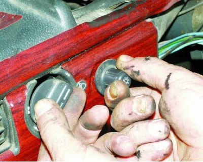
22. Remove the headlight range control handles and the instrument cluster light switch by pulling them towards you.

22. Remove the headlight range control handles and the instrument cluster light switch by pulling…


23. Loosen the instrument cluster light switch mounting nut.

23. Loosen the instrument cluster light switch mounting nut.


24. Loosen the nut securing the headlight beam corrector socket.

25. Remove the steering wheel and paddle shifters (see subsection 9.9.).

25. Remove the steering wheel and paddle shifters (see subsection 9.9.).


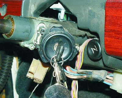
26. Turn the ignition key to position "0" to turn off the anti-theft device and disconnect the ignition switch wiring harness.
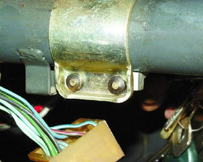
26. Turn the ignition key to position «0» to turn off the anti-theft device and disconnect the…


27. Remove the two bolts and two nuts securing the steering column pipe (see note).

Note: To prevent the lock from being removed, thereby disabling the anti-theft device, the heads of the bolts securing the lock are sheared off when tightened to a certain amount of force. If the bolt heads on your vehicle are not sheared off, unscrew the two bolts and remove the ignition switch without removing the steering column pipe.


Note: To prevent the lock from being removed, thereby disabling the anti-theft device, the heads of…


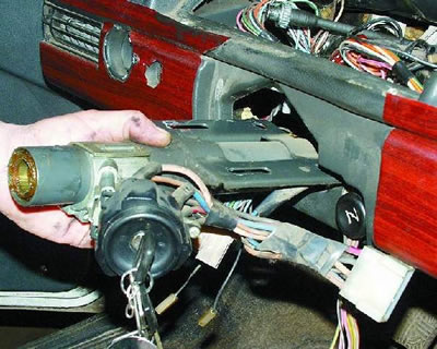
28. Remove the steering column pipe together with the ignition switch.

28. Remove the steering column pipe together with the ignition switch.


29. Pull the carburetor air damper handle (choke) towards you until a thrust appears, and remove the handle from the thrust.

29. Pull the carburetor air damper handle (choke) towards you until a thrust appears, and remove…


30. Remove the two screws securing the air damper guide rod to the instrument panel.
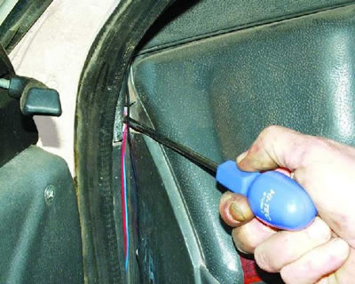
30. Remove the two screws securing the air damper guide rod to the instrument panel.


31. Loosen the screw securing the instrument panel side mount on the left side.

31. Loosen the screw securing the instrument panel side mount on the left side.


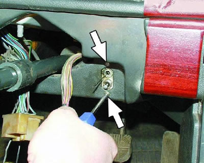
32. Remove the screw of the lower instrument panel mount on the left side.

32. Remove the screw of the lower instrument panel mount on the left side.


33. Loosen the screw securing the instrument panel side mount on the right side.

33. Loosen the screw securing the instrument panel side mount on the right side.


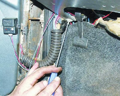
34. Remove the screw of the lower instrument panel mount on the right side.

34. Remove the screw of the lower instrument panel mount on the right side.


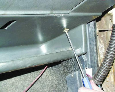
35. Loosen the screw securing the instrument panel to the glove compartment.

35. Loosen the screw securing the instrument panel to the glove compartment.


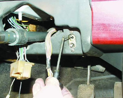
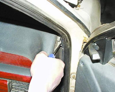
36. Remove one instrument panel console mounting screw on both sides and remove the instrument panel.

Install the panel in reverse order.

After installation, check the operation of switches and devices to ensure that they are connected correctly.


This article is available at russian, bulgarian, belarusian, ukrainian, serbian, croatian, romanian, polish, slovak, hungarian
The text was reviewed by the specialist: Grigory Vologodtsev

Share with friends:

Previous articles
VAZ-21099: Equipment and devices
Next articles

Instrument panel (high)
Windscreen wiper assembly and installation
Windscreen wiper defect detection
Disassembling the windshield wiper
Windscreen Wiper — Removal
Electrical diagram of the VAZ-21099 car
Electrical diagram of the car VAZ-21099 Lux

More articles from other manuals on VAZ cars:
➠ Removal and installation the instrument panel VAZ-1111 (1988-1996)
➠ Instrument panel — device and removal VAZ-2101 (1970-1983)
➠ Instrument panel VAZ-2105 (1979-2010)
➠ Instrument panel VAZ-2106 (1976-2006)
➠ Instrument panel — removal and installation VAZ-2107 (1982-2012)
Link in different formats to this page


Visitor comments

No comments yet


How much will 37 + 48 ?


VAZ-21099 (1990-2004) 
  • General information
  • Specifications
  • User manual
  • Maintenance
  • Car care
  • Troubleshooting
  • Power unit
  • Engine repair
  • Cooling and lubrication system
  • Power and exhaust system
  • Transmission
  • Car gearbox
  • Clutch and drive shafts
  • Chassis
  • Car suspension
  • Steering
  • Brake system
  • Body
  • Exterior
  • Interior
  • Doors and locks
  • Electrical equipment
  • Equipment and devices
  • Lighting and signaling
  • Engine electrics
  • Ignition system


VAZ-2109 (1984-1997) 
  • General information
  • Vehicle operation
  • Vehicle device
  • Power unit
  • Engine repair
  • Cooling and lubrication system
  • Supply system
  • Transmission
  • Clutch
  • Gearbox and drive
  • Chassis
  • Car suspension
  • Steering
  • Brake system
  • Body
  • Body elements
  • Electrical equipment
  • Engine electrics
  • Equipment and devices


VAZ-2108 (1984-2003) 
  • General information
  • Introduction to guide
  • Power unit
  • Engine repair
  • Cooling and lubrication system
  • Power and exhaust system
  • Transmission
  • Clutch and drive shafts
  • Car gearbox
  • Chassis
  • Front suspension
  • Rear suspension
  • Steering
  • Brake system
  • Body
  • Exterior
  • Interior
  • Doors and glass
  • Electrical equipment
  • Equipment and devices
  • Engine electrics
  • Ignition system


VAZbook.ru © 2017 · Mobile version · Contact with administration · Sitemap: EN BG BY UA RS HR RO PL SK HU · Site search · News and articles VAZ-1111 · VAZ-11113 · VAZ-2101 · VAZ-21011 · VAZ-2104 · VAZ-2105 · VAZ-21051 · VAZ-2106 · VAZ-21061 · VAZ-2107 · VAZ-21099 · VAZ-2109 · VAZ-2108 · VAZ-2110 · VAZ-2112 · VAZ-2114 · VAZ-2115 · VAZ-2121 · VAZ-21213 · VAZ-21214 ·
The site stores technical data using cookies to improve the service.