English Русский
Български
Беларускі
Український
Српски
Hrvatski
Română
Polski
Slovenský
Magyar
| Articles | Contacts | Sitemap |   
Repair and maintenance Lada Repair and maintenance Mazda Repair and maintenance Mitsubishi Repair and maintenance Toyota Repair and maintenance Land Rover Repair and maintenance Hyundai Repair and maintenance Nissan
VAZbook.ru


Main     1111   2101   2105   2106   2107   2109   2110   2115   2121  
VAZ-2108 (1984-2003) VAZ-2109 (1984-1997) VAZ-21099 (1990-2004)
  • Main
  • «Sputnik»
  • VAZ-21099
  • Electrical equipment
  • Equipment and devices
  • Disassembly and assembly of the heater fan

Disassembly and assembly of the heater fan (VAZ-21099)

            0

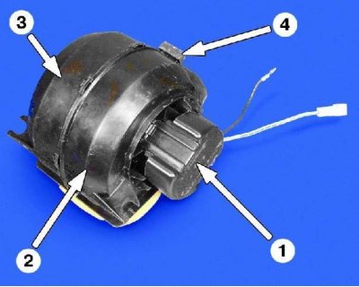
1 – Electric motor protective cover; 2 – right fan shroud; 3 – left fan casing; 4 – fan support

1 – Electric motor protective cover; 2 – right fan shroud; 3 – left fan casing; 4 – fan support


Electric motor type 45.3730


Current consumption at maximum rotation speed, A, no more than

14

Maximum fan speed, min⁻¹

4100


Disassembly and assembly of the heater fan


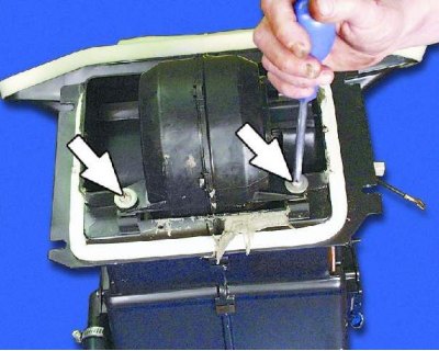
1. Remove the two screws securing the heater fan.
1. Remove the two screws securing the heater fan.


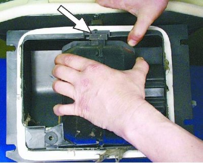
2. Remove the fan by disengaging its support.


2. Remove the fan by disengaging its support.


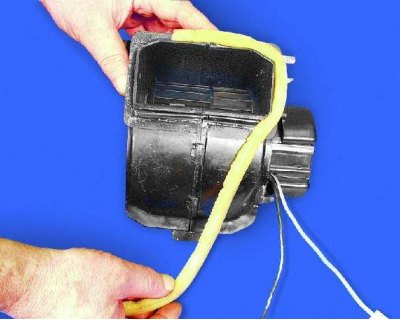
3. Peel off the foam seal from the right fan shroud.
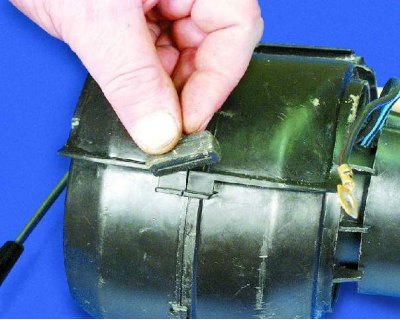
3. Peel off the foam seal from the right fan shroud.


4. Remove the support from the fan shroud.

The text is copied from the online portal VAZBOOK.ru
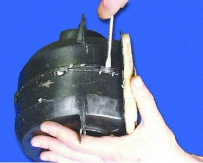
4. Remove the support from the fan shroud.


5. Using a screwdriver, pry up the plastic latches on the fan shroud and disengage them...
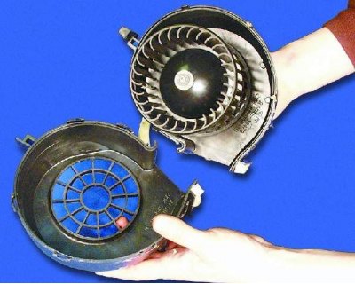
5. Using a screwdriver, pry up the plastic latches on the fan shroud and disengage them...


6....and separate the casing parts.

6....and separate the casing parts.


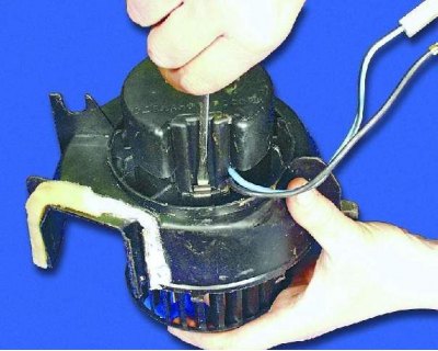
7. Unfasten the two spring latches by prying them up with a screwdriver.
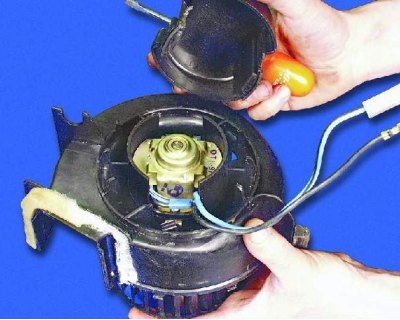
7. Unfasten the two spring latches by prying them up with a screwdriver.


8. Remove the engine cover.
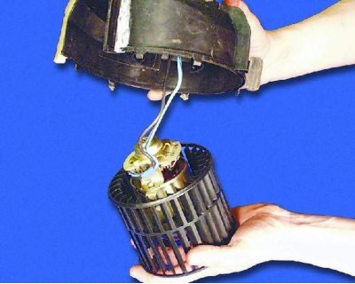
8. Remove the engine cover.


9. Remove the motor with the fan impeller.
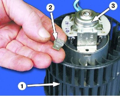
1 – fan impeller

1 – fan impeller
2 – embedded nut
3 – brush holder


Warning: Do not remove the fan impeller from the motor shaft to avoid disturbing the balance.
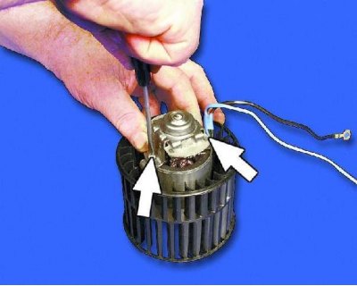

Warning: Do not remove the fan impeller from the motor shaft to avoid disturbing the balance.


10. Remove the two screws securing the brush holder.
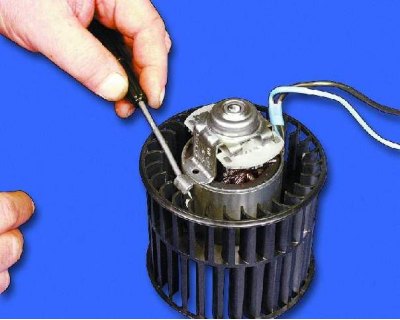
10. Remove the two screws securing the brush holder.


11. Remove the two cap nuts.
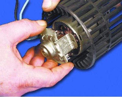
11. Remove the two cap nuts.


12. Remove the brush holder.
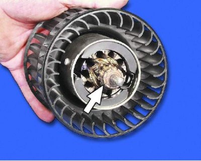
12. Remove the brush holder.


13. Inspect the manifold. If it is very dirty or has scratches, marks, or burnt areas, clean the manifold with fine sandpaper. For other faults, replace the engine.
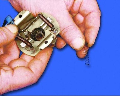
13. Inspect the manifold. If it is very dirty or has scratches, marks, or burnt areas, clean the…


14. Remove the springs from the brush guides.
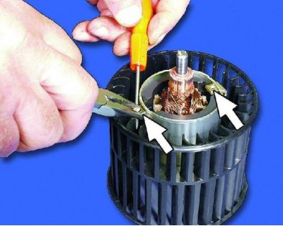
14. Remove the springs from the brush guides.


15. Insert two cage nuts.
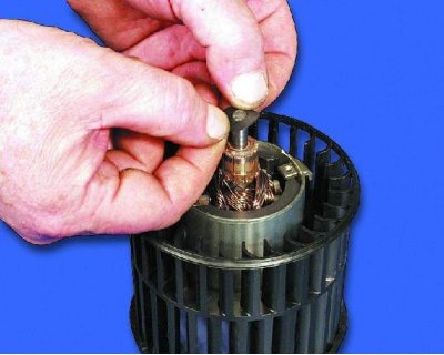
15. Insert two cage nuts.


16. Place the insulating washer on the shaft.
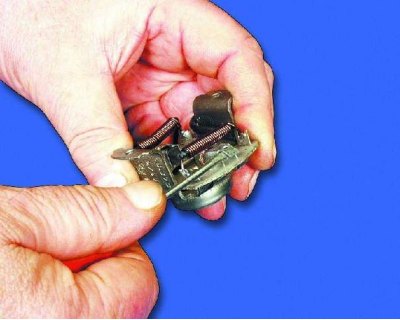
16. Place the insulating washer on the shaft.


17. Carefully bend back the edges of the guides.
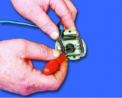
17. Carefully bend back the edges of the guides.


18. Insert the brushes into the guides until they stop.
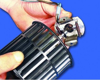
18. Insert the brushes into the guides until they stop.


19. Install the brush holder onto the motor.
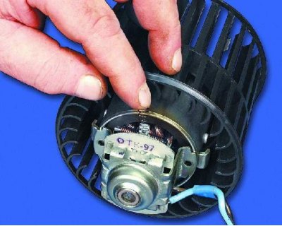
19. Install the brush holder onto the motor.


20. Insert the brush springs into the guides.
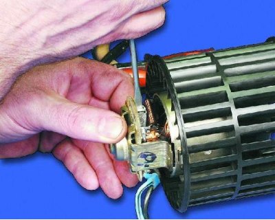
20. Insert the brush springs into the guides.


21. Bend the edges of the guides.
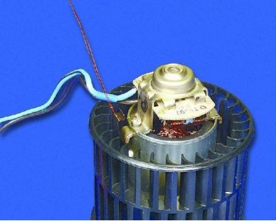
21. Bend the edges of the guides.


22. Place two spring clips onto the cage nuts.
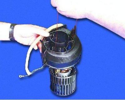
22. Place two spring clips onto the cage nuts.


23. Insert the motor into the left fan housing.
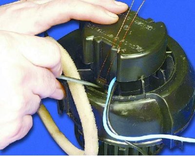
23. Insert the motor into the left fan housing.


24. Install the engine cover and secure it with spring clips (see note).
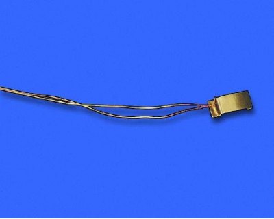
24. Install the engine cover and secure it with spring clips (see note).


Note: To make installation of the spring clips easier, tie a thin wire around them without tightening it. When installing the engine cover, hold the clips by the wire, otherwise they will be pulled off the nuts by the stator magnet.
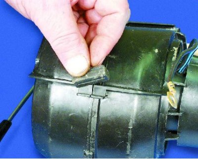

Note: To make installation of the spring clips easier, tie a thin wire around them without…


25. Connect and snap together the left and right fan casings. Place the plastic support on the casing protrusions.
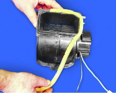
25. Connect and snap together the left and right fan casings. Place the plastic support on the…


26. Glue the foam seal to the fan casing.
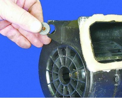
26. Glue the foam seal to the fan casing.


27. Before installation, inspect the rubber cushions and replace any that are torn or have lost their elasticity.
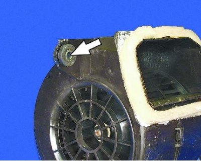
27. Before installation, inspect the rubber cushions and replace any that are torn or have lost…


28. Please note that plastic spacers are inserted into the cushions.


This article is available at russian, bulgarian, belarusian, ukrainian, serbian, croatian, romanian, polish, slovak, hungarian
The text was reviewed by the specialist: Grigory Vologodtsev

Share with friends:

Previous articles
VAZ-21099: Equipment and devices
Next articles

Removal and installation the heater fan
Removal the heater
Heater — design description
Relay and fuse box
Heater radiator
Heater rods
Heater resistor
Windscreen Wiper — Removal
Disassembling the windshield wiper

More articles from other manuals on VAZ cars:
➠ Rear window wiper, washer and heater, cigarette lighter VAZ-1111 (1988-1996)
➠ Heater motor malfunctions VAZ-2101 (1970-1983)
➠ Electric motor of the heater fan VAZ-2105 (1979-2010)
➠ Heater tap — replacement VAZ-2106 (1976-2006)
➠ Heater tap — replacement VAZ-2107 (1982-2012)
Link in different formats to this page


Visitor comments

No comments yet


How much will 11 + 21 ?


VAZ-21099 (1990-2004) 
  • General information
  • Specifications
  • User manual
  • Maintenance
  • Car care
  • Troubleshooting
  • Power unit
  • Engine repair
  • Cooling and lubrication system
  • Power and exhaust system
  • Transmission
  • Car gearbox
  • Clutch and drive shafts
  • Chassis
  • Car suspension
  • Steering
  • Brake system
  • Body
  • Exterior
  • Interior
  • Doors and locks
  • Electrical equipment
  • Equipment and devices
  • Lighting and signaling
  • Engine electrics
  • Ignition system


VAZ-2109 (1984-1997) 
  • General information
  • Vehicle operation
  • Vehicle device
  • Power unit
  • Engine repair
  • Cooling and lubrication system
  • Supply system
  • Transmission
  • Clutch
  • Gearbox and drive
  • Chassis
  • Car suspension
  • Steering
  • Brake system
  • Body
  • Body elements
  • Electrical equipment
  • Engine electrics
  • Equipment and devices


VAZ-2108 (1984-2003) 
  • General information
  • Introduction to guide
  • Power unit
  • Engine repair
  • Cooling and lubrication system
  • Power and exhaust system
  • Transmission
  • Clutch and drive shafts
  • Car gearbox
  • Chassis
  • Front suspension
  • Rear suspension
  • Steering
  • Brake system
  • Body
  • Exterior
  • Interior
  • Doors and glass
  • Electrical equipment
  • Equipment and devices
  • Engine electrics
  • Ignition system


VAZbook.ru © 2017 · Mobile version · Contact with administration · Sitemap: EN BG BY UA RS HR RO PL SK HU · Site search · News and articles VAZ-1111 · VAZ-11113 · VAZ-2101 · VAZ-21011 · VAZ-2104 · VAZ-2105 · VAZ-21051 · VAZ-2106 · VAZ-21061 · VAZ-2107 · VAZ-21099 · VAZ-2109 · VAZ-2108 · VAZ-2110 · VAZ-2112 · VAZ-2114 · VAZ-2115 · VAZ-2121 · VAZ-21213 · VAZ-21214 ·
The site stores technical data using cookies to improve the service.