
The clutch consists of a basket (pressure plate assembly) and master disk. The basket is a steel casing in which the pressure spring and the pressure plate are installed. The pressure plate is fixed in the casing on three pairs of elastic plates. From the side of the casing, the disk is pressed by a pressure spring of the diaphragm type. The clutch basket is attached with six bolts to the flywheel and is covered with an aluminum crankcase. A driven disk is installed between the pressure plate and the flywheel.
Friction linings are riveted to two sides of the driven disk. To dampen torsional vibrations at the moment the clutch is engaged, a damper with six coil springs is integrated into the driven disk. The hub of the driven disk enters splined engagement with the input shaft of the gearbox.
The clutch pedal is suspended on the same axis as the brake pedal and is attached to the body through the pedal bracket. The upper part of the clutch pedal is made as a two-arm lever. A release spring is attached to one end of it, and the upper end of the clutch release cable is attached to the other. The cable is laid in a metal sheath with a polyethylene coating. The upper end of the shell is held in the hole in the partition of the engine compartment with a rubber buffer, and the lower end is fixed with two nuts in the hole of the bracket mounted on the gearbox housing. The lower end of the rope is closed with a rubber corrugated cover. The cable is connected to the clutch fork lever through a metal leash. To prevent spontaneous disconnection of the cable with the fork lever on the leash, a protrusion A is made (see fig.).
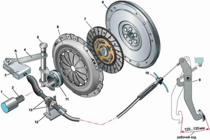
Clutch: 1 - release bearing guide sleeve; 2 - the input shaft of the gearbox; 3 - cable leash (A - ledge); 4 - clutch release fork; 5 - fork axle bushing; 6 - pressure plate assembly (basket); 7 - driven disk; 8 - flywheel; 9 - clutch pedal; 10 - buffer; 11 - clutch release clutch (release bearing); 12 - bracket on the gearbox housing; 13 - cable adjusting nuts
The clutch release fork rotates in two bushings. The upper sleeve is plastic, removable, and the lower one is bronze, pressed into the clutch housing. When the fork is turned, the force is transmitted to the pressure spring petals through an angular contact ball bearing (release bearing). The bearing is put on the clutch release clutch, through which it contacts the clutch release fork. The constant engagement of the fork and clutch is provided by a U-shaped spring. The clutch release clutch moves along the guide sleeve, put on the input shaft of the gearbox and attached to the clutch housing with three bolts.
The absence of gaps in the clutch release actuator is ensured by the clutch pedal return spring. Due to this, the clutch release clutch is pressed against the pressure spring petals, and the release bearing operates continuously. The bearing is lubricated for its entire service life.
During operation, the lining of the driven disk wears out. As the clutch pedal wears, it rises off the floor and its travel increases. Therefore, when carrying out maintenance, it is necessary to check the condition of the clutch and adjust the travel of the clutch pedal.
If the clutch disc is not replaced in time, the metal rivets for fastening the friction linings may touch the working surfaces of the pressure plate and the flywheel, leaving grooves on them.