




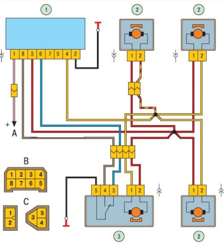
Door lock system diagram: 1 – control unit; 2 – passenger door lock motor reducer; 3 – driver's door lock motor reducer; A - to power sources; B – diagram of conventional numbering of plugs in the control unit socket; C – diagram of conventional numbering of plugs in the blocks of lock blocking gear motors.
The locking rods are driven by gear motors installed in each door. The gear motor of the left front door is equipped with a built-in switch, the contacts of which are switched when the locking button is moved or when the door lock cylinder is turned with a key. A signal is sent to unit 1 (see Fig.) via the closed contacts of the switch, and it turns on all gear motors. The control unit has an inertial switch, thanks to which the locks are unlocked when the moving car hits an obstacle, i.e. in an accident.
In case of malfunction, it is necessary to check the wires and their connections, the control unit, and the gear motors. Replace the faulty control unit and gear motors with new ones. The replacement of gear motors is described in detail in the "Body" section ("Replacing the rear door window regulator", "Replacing the front door window regulator").