




In the window lift mechanism, instead of the gear reducer used in mechanical window lifts, there is only a drum, into the hole of which the output shaft of the gear motor is inserted.
The gearmotor consists of a worm gearbox and a DC electric motor with excitation from permanent magnets. Its design is similar to the design of the gearmotor windshield wiper.
The gearmotor is reversible, the direction of rotation of the output shaft depends on the direction of the current in the anchor winding. For overload protection, it is equipped with a built-in thermal bimetallic fuse.
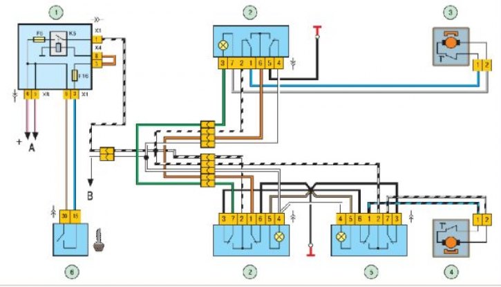
Wiring diagram for electric window lifts: 1 – mounting block; 2 – Right front door electric window switch; 3 – motor reducer of electric window lifter of right front door; 4 – motor reducer of electric window lifter of left front door; 5 – Left front door electric window switch; 6 – ignition switch; K5 – electric window switch relay; A - to power sources; B – to the outdoor lighting switch.
Gearmotors 3 and 4 (see fig.) are switched on by switches 2 and 5, located on the armrest handles. When the ignition is turned on, the supply voltage is supplied to the switches through fuse F6 and electric window relay K5, located in mounting block 1.
If the electric windows do not work, you need to remove the door trim and make sure that voltage is supplied to the gear motors, check the fuse and relay of the electric windows, and repair the broken connections in the wires. Replace the faulty gear motor with a new one.
Data for checking the gear motor:
- Motor gearbox shaft rotation speed at idle at supply voltage of (13.5±0.1) V and ambient temperature of (25±10)°C, min⁻¹….56–90
- Current consumption at the specified load and rotation speed, A…..1.2–5.0
Removal and installation electric front door windows are described in detail in the section "Body".