




Open large image in new tab »
Open large image in new tab »
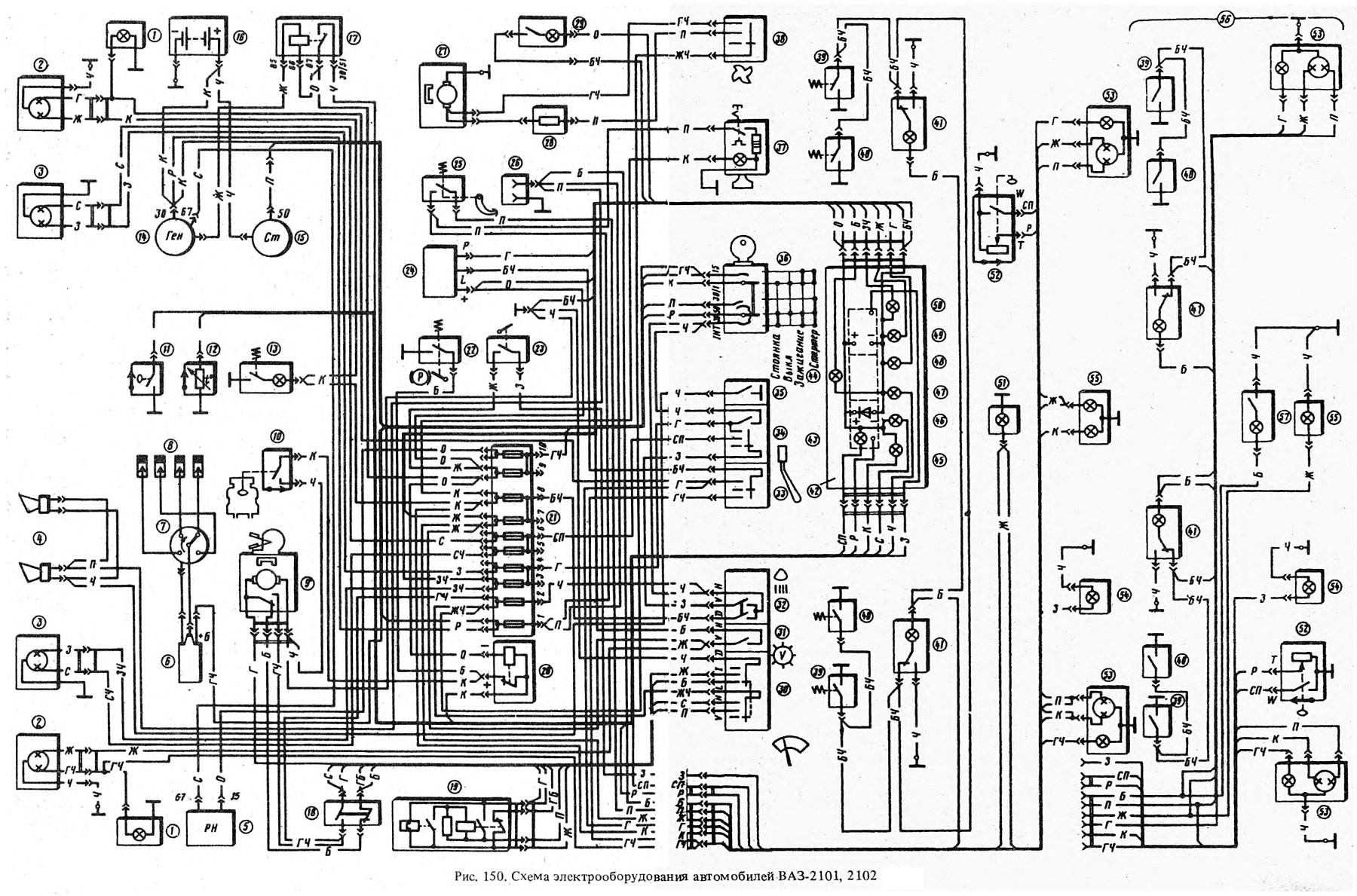
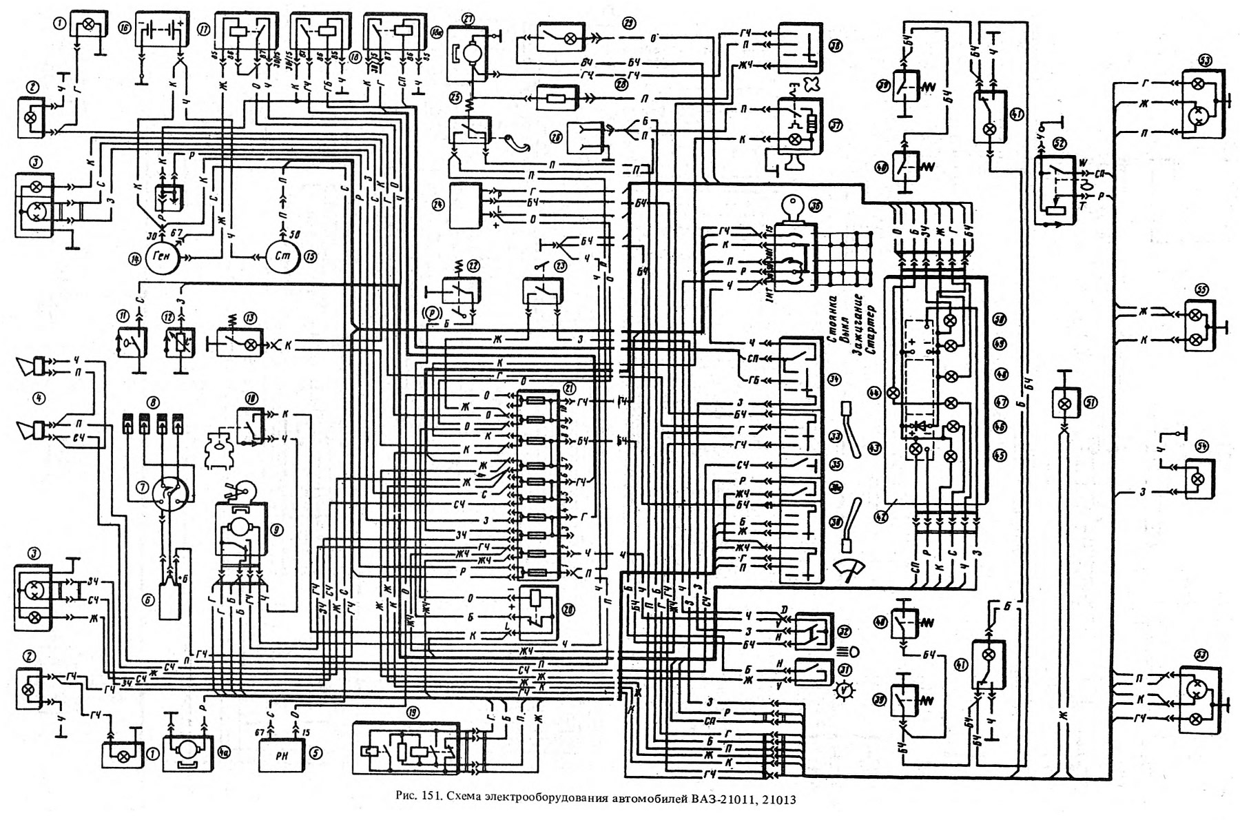
The electrical equipment diagram for vehicles 2101 and 2102 is shown in Fig. 150, and for vehicles 21011 and 21013, in Fig. 151. The following designations are used in the figures:
1 - side direction indicators; 2* - sidelights; 2** - front direction indicators; 3 - headlights; 4 - sound signals; 4a** - windshield washer motor; 5 - voltage regulator; 6 - ignition coil; 7 - ignition distributor; 8 - spark plugs; 9 - Windscreen wiper motor; 10 - Low brake fluid level sensor; 11 - Oil pressure warning light sensor; 12 - coolant temperature gauge sensor; 13 - underhood lamp; 14 - generator; 15 - starter; - battery; 17 - Battery charge indicator lamp relay; 18** - windshield wiper switch located in the windshield washer pump; 18a** - low beam headlight relay; 18a - high beam headlight relay; 19 - Windscreen wiper relay; 20 - Parking brake indicator lamp relay-interrupter; 21 - fuse box; 22 - Parking brake indicator lamp switch; 23 - Reverse light switch; 24 - turn signal relay;.25 - brake light switch; 26 - socket for portable lamp; 27 - heater electric motor; 28 - additional resistor of the heater electric motor; 29 - Glove compartment lighting lamp; 30 - Windscreen wiper switch; 30a** - windshield washer switch; 31 - Instrument cluster lighting switch; 32 - Outdoor lighting switch; 33 - direction indicator switch; 34 - headlight switch; 35 - Sound signal switch; 36 - ignition switch; 37 - cigarette lighter; 38 - Heater switch; 39 - ceiling light switches located in the rear door pillars; 40 - ceiling light switches located in the front door pillars; 41 - lampshades; 42 - instrument cluster; 43 - Fuel reserve indicator lamp; 44 - Instrument cluster lighting lamp; 45 - Parking brake and brake fluid level indicator lamp; 46 - Oil pressure indicator lamp; 47 - Battery charge indicator lamp; 48 - direction indicator lamp; 49 - external lighting control lamp; 50 - High beam indicator lamp; 51 - Trunk light; 52 - Fuel level and reserve indicator sensor; 53 - rear lights; 54 - Reversing light; 55 - Number plate light; 56* - rear wiring harness of the VAZ-2102 car; 57* - rear body lighting lamp for VAZ-2102 car.
* Only for Fig. 150.
** Only for Fig. 151.
Most circuits are turned on by the ignition switch. Always on (regardless of the position of the key in the ignition switch) power supply circuits for the sound signals, cigarette lighter, brake light, interior lighting lamps and a socket for a portable lamp.
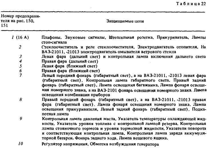
The electrical equipment of the vehicles is protected by ten fuses installed under the instrument panel on the left side of the steering column, nine of which are rated for 8 A and one for 16 A. The battery charging circuit, ignition circuit and engine starting circuit are not protected by fuses.
Before replacing a blown fuse, it is necessary to find out the reason for its burning and eliminate it. It is not allowed to use fuses that are not provided for by the design of the car.
When troubleshooting, it is recommended to look at the circuits listed in Table 22 that are protected by this fuse.
In all the diagrams given in the chapter "Electrical equipment", the color of the wires is indicated by letters, where the first letter is the color of the wire itself, and the second is the color of the stripe on the wire: B - white; G - blue; Y - yellow; 3 - (purple); O - orange; R - pink; C - gray; F - purple; Ch - black.