




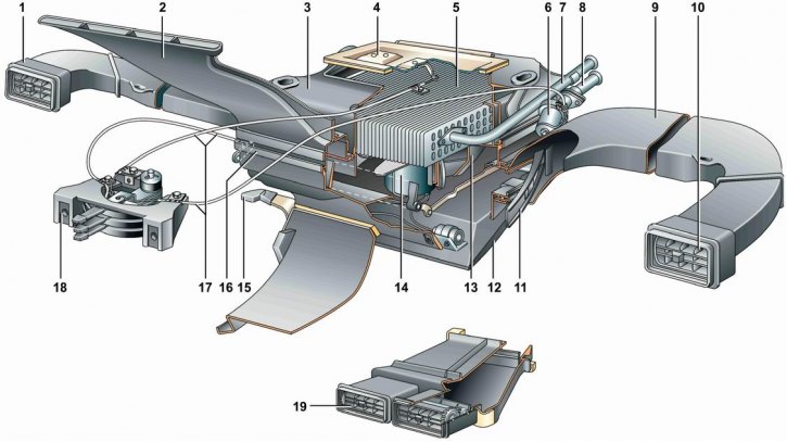
Details of the ventilation and heating system: 1 - left side window heating duct; 2 - windshield heating air duct; 3 - radiator casing; 4 - air intake cover; 5 - heater radiator; 6 - heater tap; 7 - radiator outlet pipe; 8 - radiator inlet pipe; 9 - right side window heating air duct; 10 - deflector; 11 - air duct damper; 12 - Air distribution cover; 13 - Fan guide casing; 14 - Electric fan; 15 - air distribution cover lever; 16 - fan casing; 17 - control rods; 18 - control lever bracket; 19 - central air duct (on a car with a 2107 instrument panel)
The ventilation and heating system is used to create a comfortable microclimate in the car. Ventilation and heating of the car are provided by air taken from outside. Air enters the system through the grille openings of the hood into the air intake box, located in the center in the rear part of the engine compartment and isolated from it by a rubber seal adjacent to the hood. In the air intake box, rainwater is separated from the air and flows out, and the air is directed to the heater. The heater opening is closed by the air intake cover. On a car with a model 2107 instrument panel, part of the air is diverted through the air duct from the air intake box to the central air diffusers on the instrument panel.
The heater is located in the passenger compartment and consists of a radiator casing with an air intake cover, a fan guide casing, and a fan casing with an air distribution cover, connected together with spring clips. The heater is attached with four studs to the engine compartment bulkhead reinforcement. The junction of the heater with the body is sealed with a rubber seal.
If necessary, the air passing through the heater is heated by a liquid radiator located in the casing. The inlet and outlet pipes of the radiator are brought out into the engine compartment and connected to the engine cooling system. The opening of the outlet pipes in the engine compartment shield is sealed with a rubber seal, secured with two self-tapping screws. The heater valve is built into the inlet pipe of the radiator, regulating the flow of coolant. The valve is controlled by a flexible rod from the lever of the ventilation system control unit, located on the instrument panel.
An electric fan is installed in the heater under the radiator. The fan electric motor with the impeller is mounted on two elastic cushions in the guide casing. An additional resistor is built into the electric motor power supply circuit, providing two fan rotation speeds. The fan is switched on using a three-position switch on the instrument panel.
Air ducts extend from the fan housing, directing air to both the side window deflectors and the upper windshield duct.
View the original on the internet resource VazBook
The heater air flow is controlled by closing and opening the heater covers and air flaps. The air intake cover, the flaps of the windshield heating air duct and the side air ducts are controlled by flexible rods from the levers of the handles on the ventilation system control unit. The air distribution cover of the fan casing is controlled by the handle located on it.
Main faults of ventilation and heating systems:
- leaking tap, heater radiator and pipelines and their connections;
- damage to the switch and wires, oxidation of their connections;
- failure of the electric fan.