
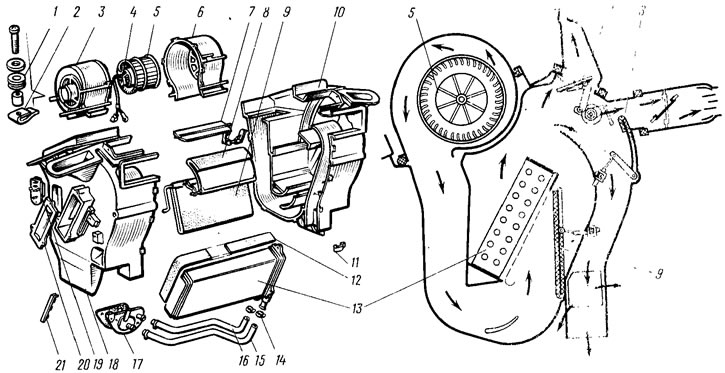
Pic. 170. Heater details: 1 - elastic sleeve; 2 - spring nut; 3 - left fan casing; 4 - electric fan; 5 - impeller; 6 - right fan casing; 7 - damper for heating century-old glass; 8 - damper for heating the legs; 9 - heater control damper; 10 - right heater casing; 11 - bracket for fastening the heater casings; 12 - gasket; 13 - radiator; 14 - clamp; 15 - supply hose; 16 - outlet hose; 17 - crane; 18 - left heater cover; 19 - resistor; 20 - sealing cover; 21 - heater control damper bracket
The heater with right 10 and left 18 casings, interconnected by brackets 11, is fixed from the cabin side with four nuts to bolts welded to the air intake box. An electric fan leans on top of the heater, consisting of 6 right and 3 left fan casings and an electric motor 4 with an impeller 5. A resistor 19 is attached to the left casing 18.
The radiator 13 is inserted into the heater casing, fastened with three screws to the right casing 10 and sealed with a gasket 12. The radiator is connected by hoses 15 and 16 to the tap 17, which is connected to the cooling system and sealed on the front panel with a gasket. The circulation of liquid through the radiator 13 is carried out by the pump of the engine cooling system.
The air supplied by the electric fan to the heater casing can enter the passenger compartment, bypassing the heater radiator, or completely pass through the radiator, or mix with part of the air that has passed through the radiator. Controlled by damper 5 (pic. 171) heater control, the lever of which is connected by a rod 19 to the lever 18. Air can be directed to the passenger compartment through the air duct 2 (pic. 172) to the heating of the windshield and through the side nozzles 3, as well as through the central nozzle 4 to the passenger compartment, and through the air duct 6 of the internal ventilation to the feet of the passengers. Windshield heating is regulated by lever 14 (see fig. 171), connected by a rod to the levers 11 of the damper 10. The lever 16 of the damper 13 regulates the flow of air to the feet of the passengers. The heater control lever 18 is simultaneously connected by a rod 1 to the heater valve lever 2.
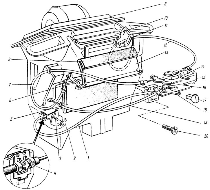
Pic. 171. Heater control: 1 - crane control rod; 2 - crane; 3 - crane lever: 4 - bracket for fastening the thrust shell; 5 - heater control damper; 6 - lever for driving the damper for heating the legs; 7 - leg warmer damper rod; 8 - seal of the foot heating damper; 9 - heater casings; 10 - damper for heating the windshield; 11 - levers for driving the damper for heating the wind speckle; 12 - windshield shutter damper rod; 13 - damper for heating the legs; 14 - control lever for the windshield heating damper; 15 - bracket for control levers; 16 - control lever for the foot heating damper; 17 - handle of control levers; 18 - heater control lever; 19 - drive rod for the heater control damper; 20 - screws for fastening the arm bracket
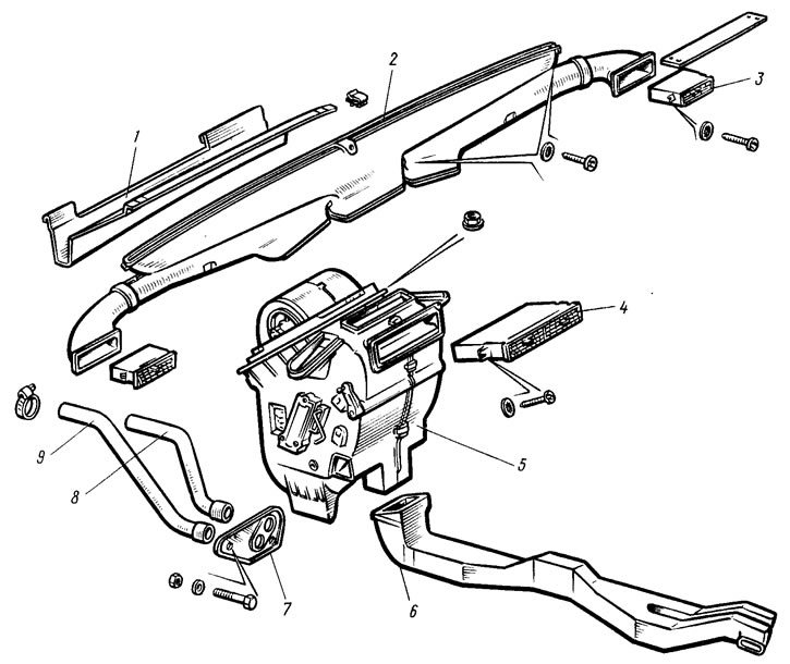
Pic. 172. Heater with air ducts and ventilation nozzles: 1 - water deflector; 2 - windshield heating air duct assembly with side window air ducts; 3 - side nozzle; 4 - central ventilation nozzles; 5 - heater assembly; 6 - air duct for internal ventilation; 7 - heater valve pipe seal; 8 - outlet rear hose; 9 - inlet rear hose
By moving the lever 18 to the right, the valve and damper 5 are opened, which directs air through the heater radiator.
By turning the guide vanes of the side and central nozzles, the direction of the air flow in the cabin is changed.
At an ambient temperature of minus 20°C, the heater provides an average temperature in the passenger compartment of plus 20°C in the maximum heating mode, and plus 25°C in the foot area.