




Contents: Removal ↓ Installation ↓
We remove the crankshaft to replace it or replace the liners.
Removal
1. Place the vehicle on an inspection pit or overpass (see "Preparing a car for maintenance and repair").
2. Remove the engine oil pan (see "Engine oil pan - removal and installation").
3. Remove the holder with the seal from the cylinder block (see "Rear Crankshaft Oil Seal - Replacement").
4. Remove the camshaft drive cover with the sealing gasket and the chain from the crankshaft sprocket (see "Timing Chain - Replacement").
5. Mark the relative positions of the connecting rods relative to their caps and the main bearing caps relative to the cylinder block.
6. With a socket wrench by 14 mm we unscrew the two nuts securing the connecting rod cover.
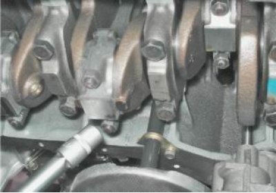
7. Remove the connecting rod cover together with the liner.
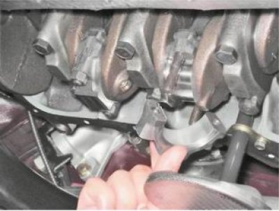
8. Disconnect the remaining connecting rods from the crankshaft and move them upward.
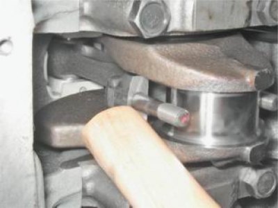
We remove the liners from the connecting rods and their caps.
9. With a socket wrench by 17 mm loosen the bolts securing the crankshaft main bearing caps.
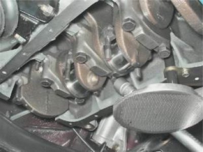
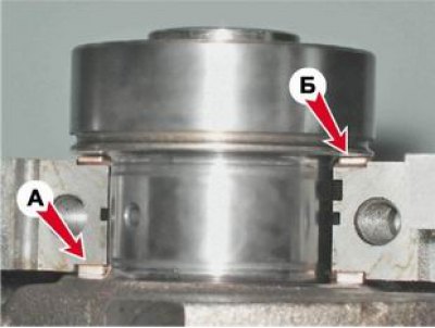
10. After unscrewing two bolts, remove the rear main bearing cover. Two thrust half rings are installed in the grooves of the rear crankshaft support. The front ring A is steel-aluminum, and the rear B is metal-ceramic. The rings can be removed by pressing on their ends with a thin screwdriver.
11. Unscrew the bolts of the remaining main bearing caps, holding the crankshaft from falling. Remove the caps one by one and take the crankshaft out of the crankcase. All cap liners (except the third), installed in the main bearing beds, have a groove. The main bearing caps have marks corresponding to their serial number (crankshaft nose reference), facing the left side of the cylinder block. On the fifth cover there are two marks, spaced apart at the edges.
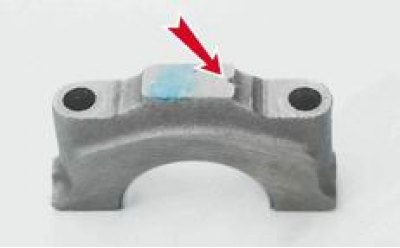
Mark of the first main bearing cap
12. To replace, remove the crankshaft main bearing shells from the cylinder block and covers.
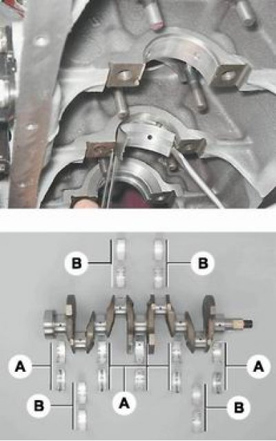
Main (A) and connecting rod (B) bearings of the crankshaft
[Information copied from the portal: VAZBOOK.ru]
Note: If there are any cracks on the journals or cheeks, the crankshaft must be replaced.
13. Using a micrometer, measure the diameters of the main and connecting rod journals and compare them with the data given in Table 8.1.27.1. If the wear or ovality is greater than 0.03 mm, the journals must be ground in a specialized workshop that has the necessary equipment (there it is also necessary to check the axial runout of the main surfaces of the crankshaft). After grinding, we re-measure the diameters of the crankshaft journals to determine the repair size of the liners.
Table 8.1.27.1. Crankshaft journal diameters
|
Nominal |
Repair (reduced) dimensions (mm) |
|||
|
025 |
050 |
075 |
100 |
|
|
Connecting rod journals |
||||
|
47,814 |
47,564 |
47,314 |
47,064 |
46,814 |
|
47,834 |
47,584 |
47,334 |
47,084 |
46,834 |
|
Root necks |
||||
|
50,775 |
50,525 |
50,275 |
50,025 |
49,775 |
|
50,795 |
50,545 |
50,295 |
50,045 |
49,795 |
Installation
1. Wash the crankshaft in kerosene and blow out its internal cavities with compressed air. Install new crankshaft main bearing shells of the nominal or repair size. On the outer cylindrical surface of the liners, numbers are stamped indicating the repair size: 025 - the first repair, for the crankshaft journal, reduced in diameter by 0.25 mm. Accordingly, the second, third and fourth repair sizes will have the following values: 050, 075, 100. It is easy to distinguish connecting rod bearings from main bearings. On the upper main bearings (except average) annular grooves are made. In addition, the bearings of the middle support are wider than the others. The connecting rod bearings are all the same and interchangeable, their diameter is smaller than the diameter of the main ones. To increase the contact area, there are no annular grooves on the connecting rod bearings.
2. Install thrust half rings into the grooves of the fifth main bearing bed with the grooves facing the crankshaft. The half rings are made of normal thickness (2,310-2,360 mm) and increased (2.437-2.487 mm).
3. Check the axial clearance between the thrust half rings and the thrust surfaces of the crankshaft, which should be within 0.06-0.26 mm. If the clearance exceeds the maximum allowable (0.35 mm),
we replace the thrust half rings with new ones, enlarged by 0.127 mm.
4. Lubricate the connecting rod and main journals of the crankshaft with engine oil and install the shaft into the block.
5. In accordance with the marks, install the main bearing caps and tighten their mounting bolts to a torque of 68.4-84.3 N·m. Check the free rotation of the shaft.
6. Install the connecting rods with liners and caps on the crankshaft. Tighten the fastening nuts to a torque of 43.4-53.5 N·m.
7. Install the engine oil pan (see "Engine oil pan - removal and installation").
8. Install the holder with the seal on the cylinder block (see "Rear Crankshaft Oil Seal - Replacement").
9. Installation of the remaining removed parts is carried out in the reverse order.
10. Adjust the chain tension (see "Timing Chain - Replacement").
11. Adjust the tension of the generator drive belt (see "Generator Drive Belt - Tension Adjustment and Replacement").
12. On a carburetor engine, check and, if necessary, adjust the ignition timing (see "Ignition timing - checking and adjustment").