




- keys "10", "13", "17" and "19"
- hexagons "5" and "10"
- screwdriver
Disconnect the wire from the "–" terminal of the battery.
Drain the fluid from the engine cooling system.
Remove the air filter (see subsection 10.10.1.).
If you detect a leak of engine oil or coolant at the joints of the cylinder head and the cylinder block, remove the head and replace its gasket. The leak may also be due to warping of the cylinder head due to engine overheating.
Attention! The cylinder head gasket is a one-time use, therefore, each time the cylinder head is removed, the gasket must be replaced.
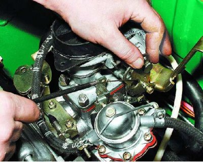
1. Remove the air damper drive rod housing from the bracket and disconnect the rod from the lever by loosening the mounting bolts (see subsection 10.10.6.).
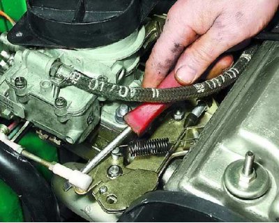
2. Disconnect the intermediate rod end from the throttle actuator intermediate lever.
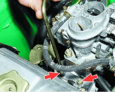
3. Unscrew the two nuts securing the intermediate lever bracket.
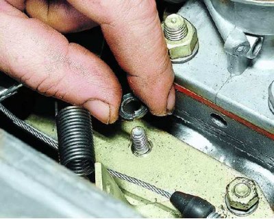
4. Please note: there are spring washers installed under the nuts.
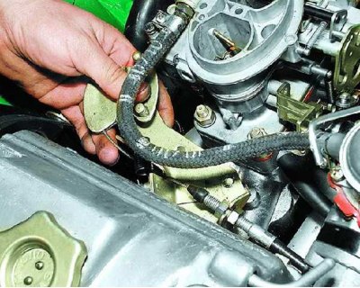
5. Remove the bracket from the studs.
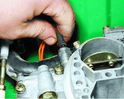
6. Disconnect the wires from the idle speed control valve.
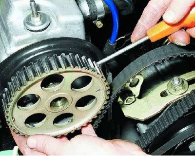
7. Remove the pulley from the camshaft (see subsection 10.4.2, operations 1–5).
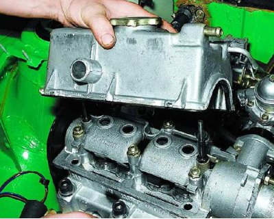
8. Remove the cylinder head cover (see subsection 10.2, operations 1–10).
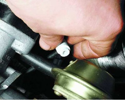
9. Disconnect the hose from the spark timing sensor vacuum regulator.
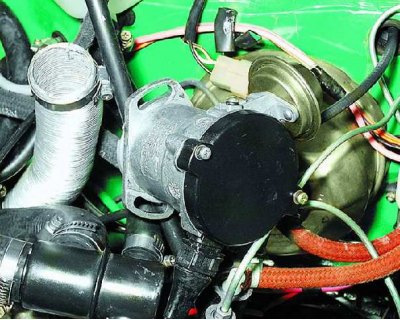
10. Unscrew the three nuts securing the spark timing sensor, remove it from the studs and move it to the side without disconnecting the wiring harness from it.
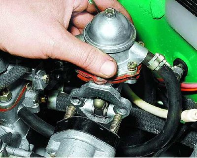
11. Remove the fuel pump from the accessory drive housing studs (see subsection 10.10.3.) and move it to the side without disconnecting the hoses from it.
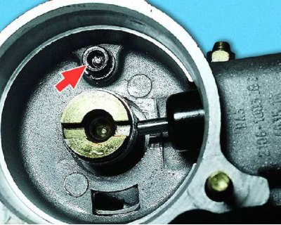
12. Loosen the auxiliary drive housing mounting bolt.
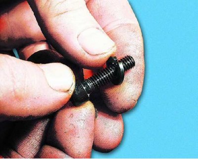
13. Please note: There is a spring washer installed under the bolt head.
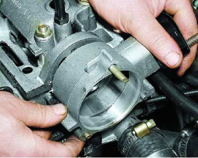
14. Remove the accessory drive housing from the studs.
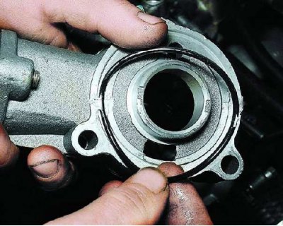
15. Check and replace the torn or loose sealing ring installed in the accessory drive housing.
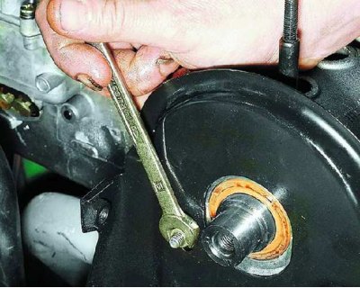
16. Loosen the upper nut of the rear cover of the camshaft drive belt.
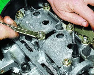
17. Remove the six nuts securing the camshaft bearing housing.
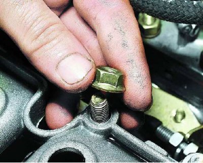
18. Please note: the nuts have serrated flanges.
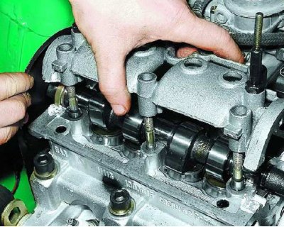
19. Remove the camshaft bearing housing.
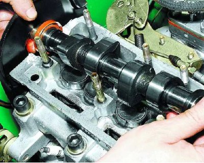
20. Remove the camshaft and remove the oil seal from it.
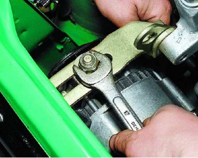
21. Loosen the nut securing the generator to the tension bar.
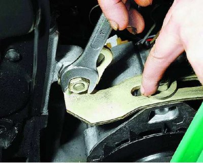
22. Loosen the nut securing the tension bar to the cylinder block and remove the flat washer installed underneath it.
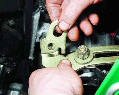
23. Remove the eye from the pin.
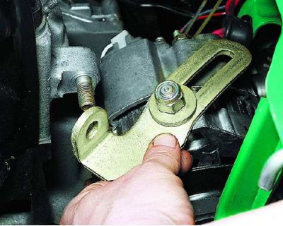
24. Remove the tension bar from the stud.
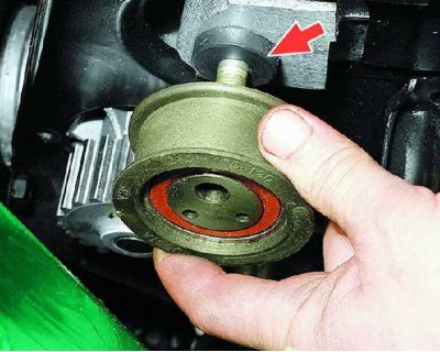
25. Remove the tension roller and spacer ring (see subsection 10.3.1.).
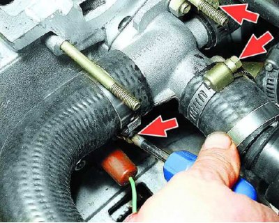
26. Loosen the clamps and disconnect the three hoses from the cooling jacket pipe.
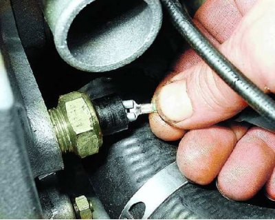
27. Slide the protective cap and disconnect the wire from the coolant temperature gauge sensor.
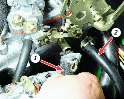
28. Loosen the clamps and disconnect the vacuum hose 1 from the inlet pipe fittings (to the vacuum booster) and hose 2 for heating the inlet pipe.
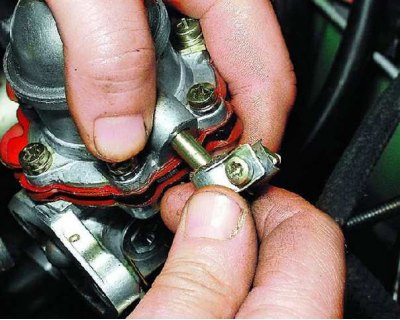
29. Loosen the clamp and disconnect the fuel supply hose from the fuel pump to the carburetor.
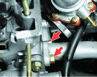
30. Unscrew the two nuts securing the muffler inlet pipe on the left side of the head.
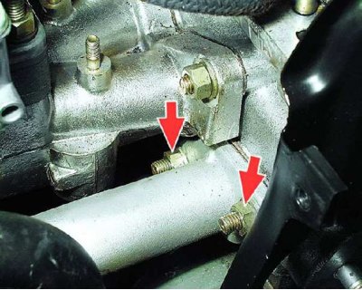
31. Unscrew the two nuts securing the intake pipe on the right side of the head.
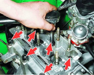
32. Remove the six cylinder head mounting bolts.
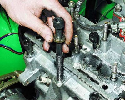
33. Remove the bolts and washers.

34. Press the rear camshaft drive belt cover until the stud comes out of its hole.
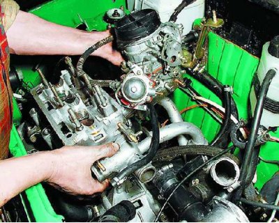
35. Remove the head from the cylinder block by removing the studs from the holes in the flanges of the muffler inlet pipe.
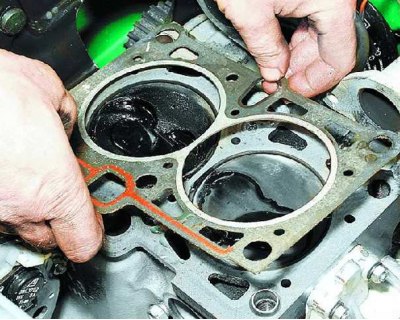
36. Remove the gasket.
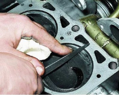
37. Clean the mating surfaces of the cylinder block and head.
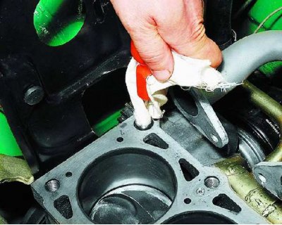
38. Remove oil from the threaded holes in the cylinder block under the head mounting bolts.
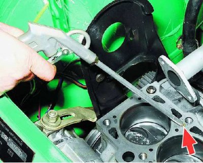
39. Blow out the jet in the oil channel of the cylinder block with compressed air.
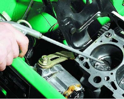
40. Blow out the block cylinders with compressed air.
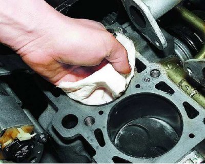
41. Wipe the cylinder bores and the cylinder block mating surface thoroughly with a clean cloth.
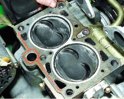
42. Install a new gasket on the cylinder block. It must be clean and dry.
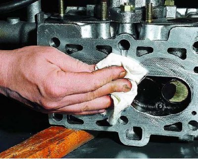
43. Wipe the cylinder head mating surface thoroughly with a clean cloth.
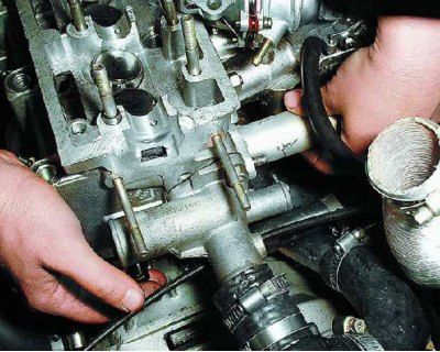
44. Install the head on the block, placing the flanges of the muffler inlet pipe on the head studs.
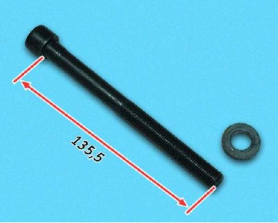
45. Measure the length of the cylinder head bolts, as they stretch with repeated use. Replace bolts longer than 135.5 mm with new ones.
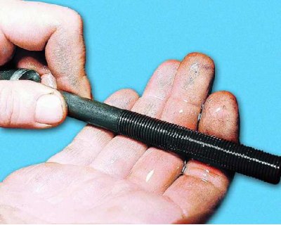
46. Lubricate the cylinder head mounting bolts and washers with a thin layer of engine oil.
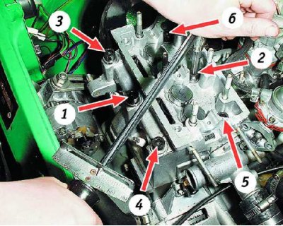
47. Tighten the head bolts in the following four steps in the sequence shown:
- 1st – torque 20 N/m (2 kgf/m)
- 2nd – torque 69.4–85.7 N/m (7.1–8.7 kgf/m)
- 3rd – turn 90°
- 4th – finally turn 90°
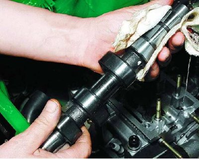
48. Wipe the camshaft thoroughly with a clean cloth.
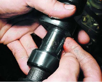
49. Lubricate the camshaft journals and cams with a thin layer of engine oil.
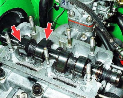
50. Install the camshaft into the cylinder head so that the valve cams of the first cylinder are directed upward from the valve lifters.
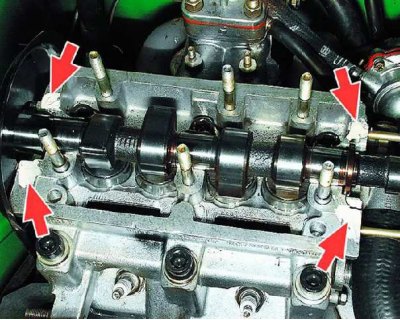
51. Apply sealant to the cylinder head surface where the bearing housing meets.
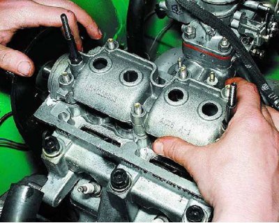
52. Install the camshaft bearing housing.
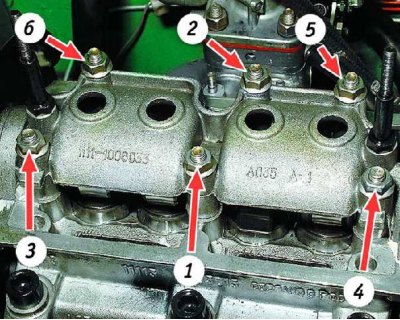
53. Tighten the bearing housing nuts in the order shown in two stages:
- 1st - tighten the nuts until the bearing housing touches the cylinder head surface;
- 2nd – finally tighten the nuts to a torque of 21.6 Nm (2.2 kgf/m).
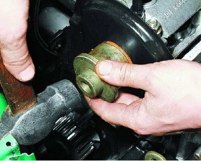
54. Press in the camshaft oil seal (see subsection 10.4.2.). Install the parts on the head and connect the hoses and wires to it in the reverse order of removal. Install the camshaft drive belt (see subsection 10.3.2.). Check and, if necessary, adjust the valve clearances (see subsection 10.2.).