
The timing mechanism includes: camshaft belt drive, camshaft 5 (pic. 19), exhaust and intake valves 2, valve springs with fastening parts and pushers 3 with shims 6. The camshaft cam acts on the valve through the pusher 3. This mechanism design provides a rigid and reliable kinematic connection between the cam and the valve, thereby reducing the vibration level of the parts.
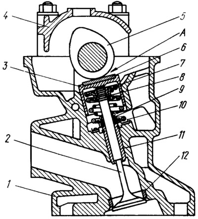
Pic. 19. Section of the cylinder head but the intake valve:
1 - cylinder head: 2 - valve; 3 - pusher; 4 - camshaft bearing housing; 5 - camshaft; 6 - adjusting washer; 7 - a plate of springs; 8 - valve cracker; 9 - oil deflector cap; 10 - spring washer; 11 - guide sleeve; 12 - valve seat; A is the gap between the adjusting washer and the camshaft knuckle.
The working cycle in the engine cylinder occurs within two revolutions of the crankshaft, i.e., in four successive strokes (tact) piston: intake of a combustible mixture into the cylinder; compression; the working stroke at which combustion and expansion of the mixture occur; release of exhaust gases. Combustible mixture intake and exhaust gas processes (valve timing) provided with timely opening and closing of the corresponding valves (pic. 20).
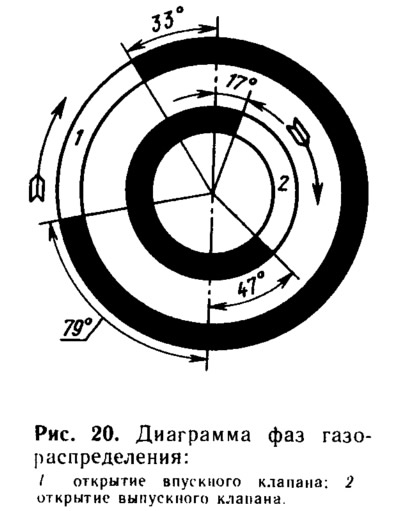
The intake valve begins to open even before the start of the intake stroke, i.e., before the piston approaches the V. M. T. at a distance corresponding to 33°of the crankshaft rotation. This is necessary so that the valve is fully opened by the time the piston goes down. Then more fresh combustible mixture will flow through the inlet.
The inlet valve closes with a delay, i.e., after the piston passes N.M.T. at a distance corresponding to 79°of the crankshaft rotation. Due to the inertial pressure of the jet, the combustible mixture continues to flow into the cylinder when the piston has already begun to move upward.
The exhaust valve begins to open even before the end of the working stroke, i.e., before approaching the N.M.T., at a distance corresponding to 47°of the crankshaft rotation. At this moment, the pressure in the cylinder is still quite high, and the gases begin to intensively exit the cylinder, as a result of which their pressure and temperature drop rapidly. This greatly improves the cleaning of the cylinder from exhaust gases and protects the engine from overheating. The release is completed after the piston has passed the V.M.T., i.e., after the crankshaft has rotated another 17°.
From the valve timing diagram, it can be seen that there is such a period (during 50°crankshaft rotation), when both valves, intake and exhaust, are open at the same time. Due to the short time interval, valve overlap does not lead to the penetration of exhaust gases into the intake manifold; on the contrary, the inertia of the outgoing exhaust gas flow causes the combustible mixture to be sucked into the cylinder and thereby improves its filling.
Cylinder head
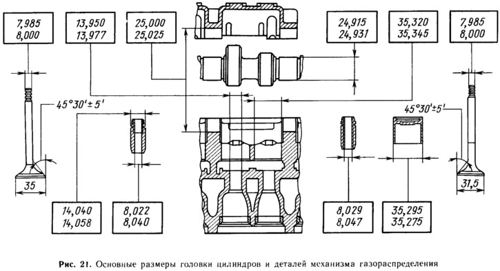
Details of the gas distribution mechanism are installed on the cylinder head. The main dimensions of the cylinder head and parts of the gas distribution mechanism are given in fig. 21.
The four-cylinder head is cast from an aluminum alloy. It is exposed to high temperatures and gas pressures. Therefore, it has a rigid lower support part, which is intensively cooled by liquid. The wall thickness is made as uniform as possible in order to reduce internal stresses from thermal expansion.
In the cylinder head there are wedge-shaped combustion chambers with inlet and outlet channels, which are brought to the right side and are connected through gaskets to the corresponding pipelines. Each combustion chamber has threaded spark plug holes on the left side of the cylinder head. On the left side there are also two channels for draining oil into the oil sump.
The free space inside the cylinder head forms a cooling jacket, which on the rear side has an outlet to the outlet pipe. The sensor for the coolant temperature gauge is also screwed in on this side. Through holes on the underside, the cooling jacket of the cylinder head communicates with the cooling jacket of the cylinder block. On the right side, through two holes, the coolant passes into the intake manifold jacket to heat the combustible mixture.
In the upper right part, a channel for the oil line is drilled along the entire cylinder head, from which oil is supplied through inclined channels to the camshaft bearings, and through a horizontal channel to the right side to the oil pressure warning lamp sensor.
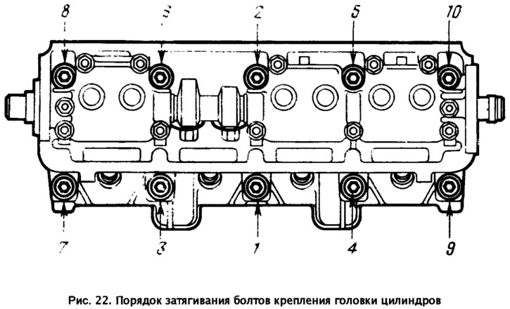
The head is attached to the cylinder block with ten bolts. For a uniform and tight fit, the bolts must be tightened on a cold engine in a certain sequence (pic. 22) and in four steps: 1st - pre-tighten the bolts with a torque of 2 kgf·m; 2nd - tighten the bolts with a torque of 7.1... 8.7 kgf·m, 3rd - tighten the bolts by 90°; 4th - again tighten all the bolts by 90 Since the bolts are tightened to the yield point, they are pulled out. Therefore, bolts can only be reused if they have stretched to a length of no more than 135.5 mm (without bolt head). Two centering sleeves around bolts 8 and 9 (see fig. 22) ensure the exact relative position of the head and cylinder block.
In the upper part of the cylinder head there are five bearings for the camshaft journals. The supports are detachable. The top half is in the bearing housings (front and rear), and the lower one in the cylinder head. The bearing holes are machined complete with bearing housings, so they are not interchangeable and the cylinder head can only be replaced complete with bearing housings.
The valve drive mechanism mounted on the cylinder head is closed with an aluminum cast cover. A groove runs along the entire perimeter of the lower surface of the cover, into which a sealing rubber gasket is inserted. The fastening studs are also insulated from the cover with rubber bushings. Thus, the cover does not come into direct contact with the cylinder head. Therefore, vibration from the cylinder head is not transmitted to the cover and noise from the gas distribution mechanism is reduced.
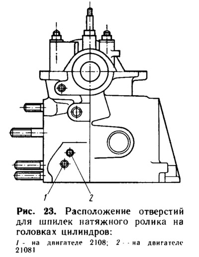
Engines 21081 and 2108 use the same cylinder heads. But they have a difference in the installation location of the tension roller stud. On engines 2108, the stud is wrapped in the bottom hole 1 (pic. 23), and on engines 21081 - in the upper hole 2.
The cylinder head of the 21083 engine differs from the 2108 head in the increased intake valve diameters - 37 mm instead of 35 mm. Accordingly, the diameters of the inlet valve seats and the diameters of the inlet channels of the cylinder head are increased. The number of the cylinder head is cast on its left side, which, due to the transverse arrangement of the engine on the car, is the front.
Cylinder head gasket
The cylinder head gasket is designed to provide a seal between the block and the cylinder head. It has a steel frame lined with asbestos on both sides. The frame keeps the asbestos from spreading. The edges of the holes for the cylinders are edged with aluminized steel, the hole for the passage of oil to the camshaft is with copper tape, and the holes for draining oil into the crankcase have an additional sealing coating in the form of a natural rubber roller 2 mm wide and 0.035 mm high.
When assembling the engine, always install a new gasket. A used gasket must not be used as it will not seal. When installing the gasket, you should pay attention to the fact that the hole for the passage of oil (edged with copper tape) located in the area of the 5th cylinder head bolt (bolt number see fig. 22).
On engines 2108 and 21081, the same gaskets are used, and on 21083 - another, with enlarged holes for the cylinders. They are easy to distinguish by their appearance. So, for gasket 21083, the jumper between the holes for the cylinders is only 5 mm, and the holes themselves have the shape of a circle. At gasket 2108, the holes for the cylinders have a complex configuration, and the jumper between them is 7.9 mm.
The valve seats are made from special cast iron to provide high impact strength. Inlet valve seats are pressed into the cylinder head with an interference of 0.081... 0.121 mm, and exhaust valves - 0.071... 0.111 mm.
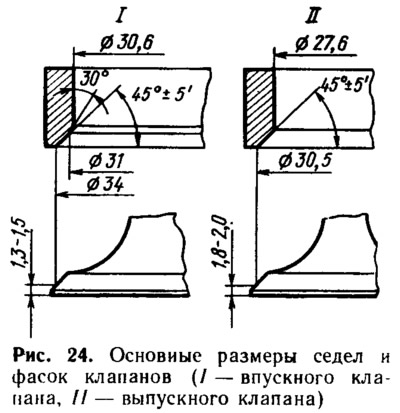
This interference is necessary to ensure that the seats are securely held in the cylinder head under conditions of high temperatures and shock loads. To facilitate the installation of seats, they are either cooled in liquid nitrogen to -175°C before being pressed in, or the cylinder head is heated to 80°C. Working chamfers of valve seats (pic. 24) after pressing, they are processed in assembly with the cylinder head to ensure accurate alignment of the chamfers and holes of the guide bushings.
Valve guides
Valve guide bushings are made of cast iron and are pressed into the cylinder head with an interference fit of 0.063... 0.108 mm. On their outer surface there is a groove into which a steel retaining ring is inserted. It ensures the accuracy of the position of the bushings during pressing and protects them from possible falling out.
The holes in the bushings are processed after they are pressed into the cylinder head. This provides a narrow tolerance for the bore diameter and the accuracy of its location in relation to the working chamfers of the valve seat. In the holes of the guide bushings, spiral grooves are made for lubrication. The inlet valve bushings are grooved up to half the bore length, and the exhaust valve bushings are grooved along the entire length of the bore.
On top of the guide bushings, caps made of heat-oil-resistant rubber with a steel reinforcing ring are put on, which cover the valve stem and serve to reduce the penetration of oil into the combustion chamber through the gaps between the guide bushing and the valve stem.
Valves
The inlet valve is made of chromium-nickel-molybdenum steel. For better filling of the cylinder, its plate has a slightly larger diameter than the exhaust valve plate.
The exhaust valve operates at high temperatures in an aggressive exhaust gas environment. Therefore, it is welded from two parts. The valve stem is made of chromium-nickel-molybdenum steel, which has high wear resistance and thermal conductivity for efficient heat removal from the valve disc to its guide sleeve. Heat-resistant chromium-nickel-manganese steel is used for the valve disc. In addition, to reduce the wear of the valve face, a special heat-resistant alloy is welded onto it.
To increase the wear resistance of the rods, both valves are nitrided, and the upper part of the rod is hardened by high frequency currents.
The springs press the valve against the seat and prevent it from breaking away from the pusher. To avoid resonant vibrations, two springs are installed - external and internal (see fig. 19) twisted to one side. The lower ends of the spring lie on the support washer. The upper support plate of the springs is held on the valve stem by two crackers, which, when folded, have the shape of a truncated cone.
Pushers 3 (see fig. 19) valves transmit force from the camshaft cam to the valve. They are steel cylindrical The surface in contact with the valve is nitrocarburized to a depth of 0.2 mm to increase wear resistance. At the top of the pushers there is a slot for an adjusting washer.
Adjusting washers b (see fig. 19) — flat steel nitrocarburized to a depth of 0.6 mm. By selecting their thickness, the gap A between the cam and the washer is adjusted. Spare parts are supplied with washers with a thickness of 3 to 4.5 mm at intervals of every 0.05 mm. Washer thickness (numbers) is marked by an electrochemical method on its lower surface.
The camshaft is a rod with cams and bearing journals The shape and arrangement of the cams ensure that the valves open and close in accordance with the order of operation of the cylinders (1—3—4—2) and valve timing (see fig. 20).
Camshaft - cast iron five-bearing. On its rear side there is an eccentric for driving the fuel pump, and on the shank there is a groove for connecting to the clutch of the ignition distributor sensor. The working surfaces of the cams, the eccentric and the surface under the stuffing box are bleached to increase wear resistance. This process consists in electric arc melting of surfaces, as a result of which a layer of the so-called «white» cast iron with high hardness.
To prevent axial movement of the camshaft, a flange is provided at its rear end, which is fixed between the cylinder head (with bearing housing) and accessory housing. The front end of the camshaft is sealed by a self-moving rubber seal.
Bearing housings
Camshaft bearing housings. The camshaft bearing journals rotate in holes that are half made in the cylinder head and half in the bearing housings (front and rear). Bearing housings are cast aluminium. In the front case are the first and second, in the back - the third, fourth and fifth support. The gap between the holes of the supports and the camshaft journals lies in the range of 0.069... 0.11 mm. Maximum allowable clearance (wear) - 0.2 mm.
Each bearing housing is centered relative to the cylinder head by two locating sleeves that are put on the mounting studs. To prevent oil from leaking from under the bearing housings, a liquid self-hardening sealant of the SUPER THREE BOND No 50 type or a domestically produced KLT-75T sealant similar to it is used. It is produced in tubes; when assembling the engine, it is applied with a flagellum to the surface of the cylinder head in the area of the extreme camshaft bearings.
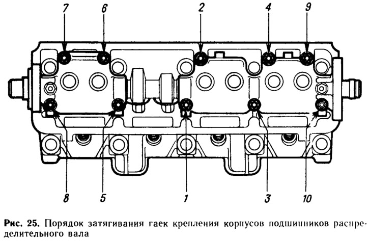
To prevent breakage or warping of the bearing housings, the camshaft should be placed in the supports, turning the cams of the first cylinder up, and tightening the fastening nuts must be done in a certain sequence (pic. 25) and in two steps. First, pre-tighten the nuts until the surfaces of the bearing housings are in contact with the cylinder head. In this case, the mounting sleeves of the housings must freely enter their sockets. Then finally tighten the fastening nuts to a torque of 2.2 kgf·m, following the same sequence.
Camshaft drive
The camshaft drive consists of a toothed drive pulley 1 (pic. 26) on the crankshaft, the driven toothed pulley 5 on the camshaft, the tension roller 3 and the toothed belt 6. The pulley 2 of the coolant pump is also driven by the same belt. The belt drive operates in a dry environment, without lubrication. From dust and dirt, it is closed by the front plastic and rear steel protective covers.
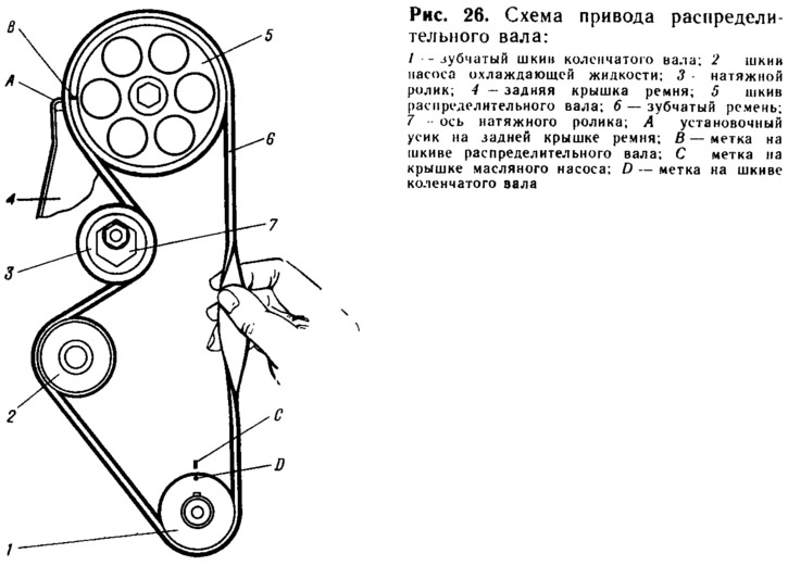
Pic. 26. Camshaft drive scheme:
1 - spongy pulley of the crankshaft; 2 - coolant pump pulley; 3 - tension roller; 4 - rear belt cover; 5 - camshaft pulley; 6 - toothed belt; 7 - axis of the tension roller; A - installation antennae on the back cover of the belt; B - mark on the camshaft pulley; C - mark on the oil pump cover; D - mark on the crankshaft pulley.
The peculiarity of the drive is a toothed elastic belt with semicircular teeth. It is made of oil-resistant rubber reinforced with fiberglass cord. The teeth are covered with an elastic cloth to increase wear resistance. The cord and fabric shell are bonded to the rubber during the vulcanization process and give the belt high strength. Two branches of the belt together withstand a tensile force of up to 1200 kgf.
The tension of the belt is carried out by the tension roller 3, which rotates on the eccentric axis 7. By turning the axis relative to the fastening pin, you can change the position of the center of rotation of the roller.
To match the opening and closing moments of the valves with the angles of rotation of the crankshaft (i.e. to ensure the correct installation of the valve timing), crankshaft and camshaft pulleys are marked «IN» and «D». There is a mark on the back cover of the toothed belt «A» (recurved tendril), and on the cover of the oil pump there is a mark «WITH». If the valve timing is set correctly, then when the piston of the first cylinder is in V.M.T. at the end of the compression stroke, the mark «IN» on the camshaft pulley must match the mark «A» on the back cover, and the label «IN» on the crankshaft pulley - with a mark «WITH» on the oil pump cover.
On the car, the engine is located so that the marks «WITH» and are located in a poorly visible area. Therefore, it is also possible to control the position of the crankshaft by the mark on the flywheel and the scale in the hatch of the clutch housing (see fig. thirty).