




Contents: Disassembly ↓ Assembly ↓
To perform the work you will need fixing glue, an impact screwdriver, primary and secondary shaft seals, a set of gaskets, and a torque wrench.
Disassembly
1. Drain the oil from the gearbox (see "Gearbox - Checking the level and changing the oil").
2. Remove the gearbox (see "Gearbox - removal and installation").
3. Clean with a brush and wash the outer surface of the box with kerosene or white spirit.
4. Remove the release bearing sleeve and the clutch release fork from the gearbox (see "Clutch parts - removal and installation").
5. Disconnect the elastic coupling of the cardan shaft from the flange on the secondary shaft of the gearbox (see "Cardan transmission - disassembly and assembly").
6. Remove the elastic coupling flange from the secondary shaft of the gearbox (see "Secondary shaft seal - replacement").
7. Disconnect the power unit support with the cross member from the rear cover of the gearbox (see "Powertrain Mounts - Replacement").
8. Remove the speedometer drive (see "Speedometer Drive - Replacement").
9. Remove the reversing light switch (see "Reverse Light Switch - Checking and Replacing").
10. Remove the cuff from the ball joint of the gear shift lever.
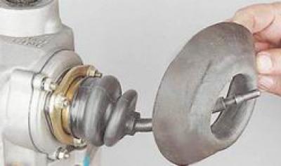
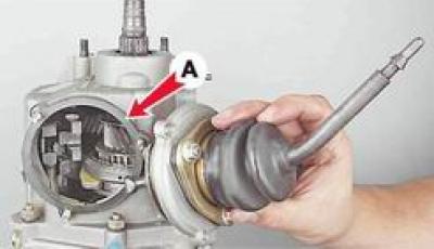
11. Key by 10 mm we unscrew the three nuts securing the gear shift lever housing to the rear cover of the crankcase.

12. Remove the lever housing and sealing gasket from the studs A underneath it.
13. With a socket wrench by 13 mm we unscrew the two nuts securing the bracket of the exhaust system's inlet pipe.
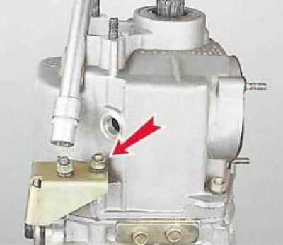
14. Remove the bracket and take out the square-headed anchor bolt located underneath it.

15. With socket and open-end wrenches by 13 mm we unscrew the five nuts securing the rear cover.
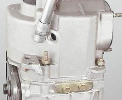
16. With a socket wrench by 10 mm we unscrew the ten nuts securing the bottom cover.
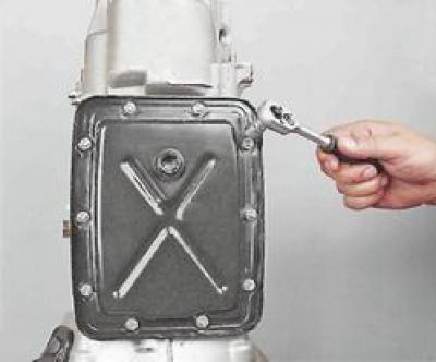
17. Remove the cover and the gasket underneath it.
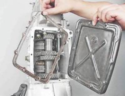
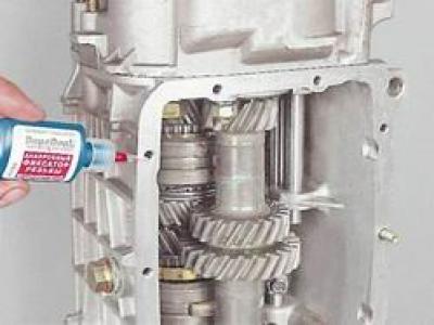
18. Some nuts unscrew together with the studs. In this case, after washing the threaded holes and studs with solvent, apply fixing glue according to the instructions and install the studs in place.
19. Key by 13 mm we unscrew the remaining nut securing the rear cover, located inside the crankcase.
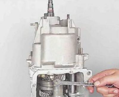
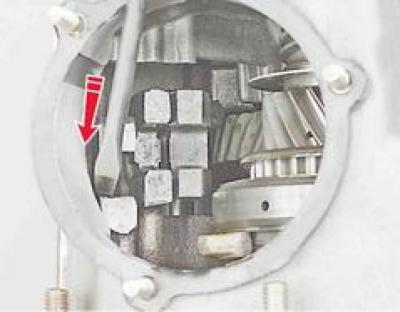
20. To make it easier to remove the rear cover, use a screwdriver to push down the rod for engaging the first and second gears. This engages the second gear.
21. Tapping the cover with a hammer with a rubber or wooden striker along the perimeter of the mounting plane, we disconnect it from the gearbox housing.
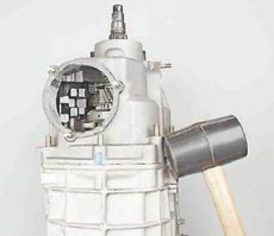
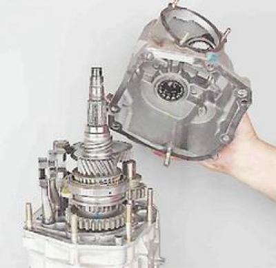
22. Remove the rear cover from the studs and then, turning it clockwise, remove it from the crankcase. The gasket installed between the cover and the crankcase may tear. Install a new gasket during assembly.
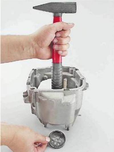
23. Remove the plastic plug of the V-gear and reverse gear block from the rear cover by pushing it out with a suitable tool through the hole in the bearing.
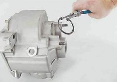
24. Using pliers, remove the thrust ring of the bearing of the 5th gear and reverse gear block from the groove in the cover.
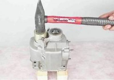
25. To avoid damaging the back cover, place it on two wooden blocks and use a hammer (through a mandrel of suitable diameter) we press out the bearing of the V-th gear block and the reverse gear. The inner ring of the bearing, as a rule, remains on the shaft of the block.
26. Remove the bearing.
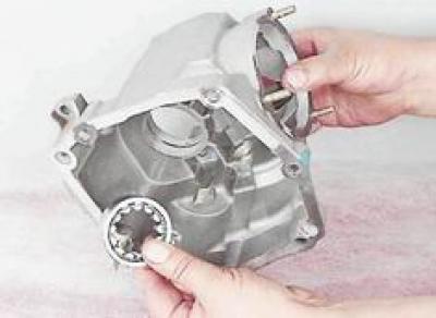
27. Remove the secondary shaft seal from the hole in the rear cover (see "Secondary shaft seal - replacement").
28. Remove the thrust washer of the inner ring of the secondary shaft rear bearing.
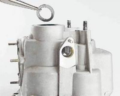
29. Using a mandrel of suitable diameter, press out the rear bearing of the secondary shaft and remove it.
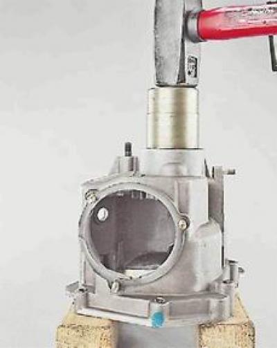
30. Remove the inner ring of the rear bearing from the secondary shaft.
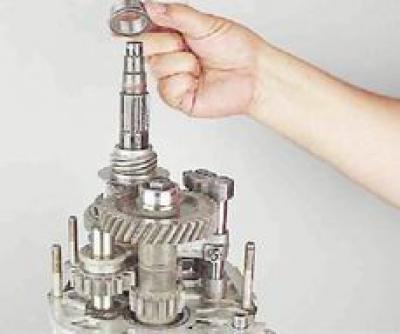
We assemble the bearing by tying its parts together with wire or twine.
31. Remove the speedometer drive gear and the retaining ball A gear located in the groove of the shaft.
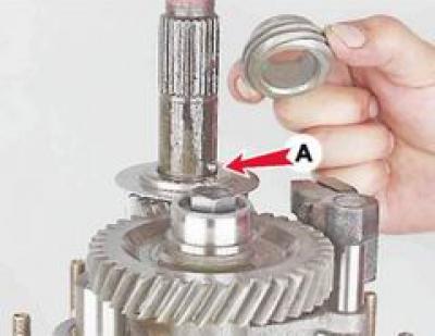
32. Remove the oil deflector washer.
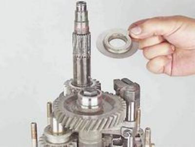
33. Key by 10 mm we unscrew the bolt securing the fork for engaging the 5th gear and reverse gear.
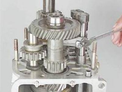
34. To block the rotation of the shafts, move the intermediate gear A reverse gear, including reverse gear. The second gear was previously engaged when the rear cover was removed. If it was disengaged, press the rod B. With a socket wrench by 17 mm loosen the bolt securing the V-gear and reverse gear block without completely unscrewing the bolt.
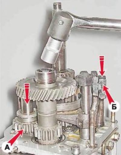
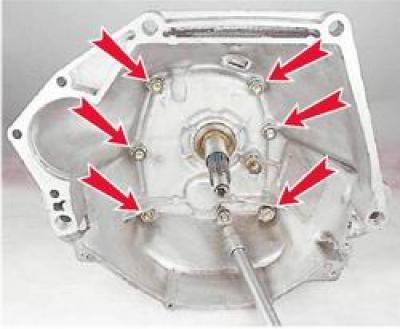
35. With a socket wrench by 13 mm unscrew one nut securing the clutch housing to the gearbox and use a socket wrench by 17 mm we unscrew the remaining six nuts.
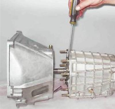
36. Using a screwdriver, disconnect the clutch housing from the gearbox and remove the sealing gasket.
37. To replace the primary shaft seal, use a punch to press it out through the hole in the flange of the front gearbox cover.
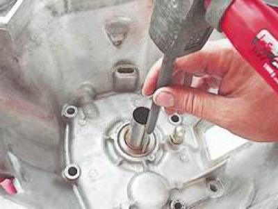
38. Using pliers, remove the oil seal from the front cover of the gearbox.
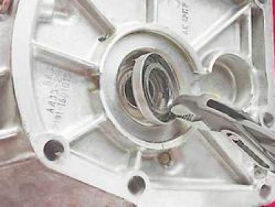
39. Remove the spring ring from the primary shaft of the gearbox. The ring has a conical shape and is installed with the smaller diameter towards the bearing.
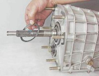
40. With a socket wrench by 19 mm we unscrew the bolt securing the front bearing of the intermediate shaft and remove the bolt together with the spring and clamp washers.
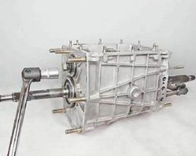
41. With a socket wrench by 17 mm finally, unscrew and remove the gear block mounting bolt.
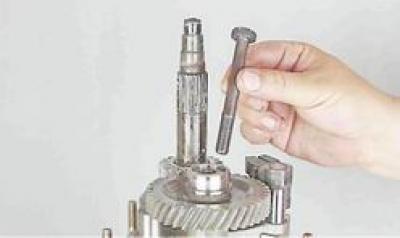
42. By moving the V-gear engagement fork along the rod, we remove the gear block from the intermediate shaft.
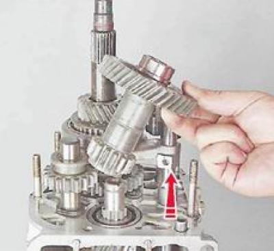
43. Place the gear block in a vice and use two large screwdrivers to press off the inner ring of the intermediate shaft rear bearing.
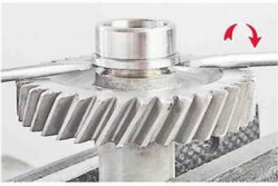
We assemble the bearing and tie its parts together with wire or twine.
44. Remove the spacer washer from the secondary shaft.
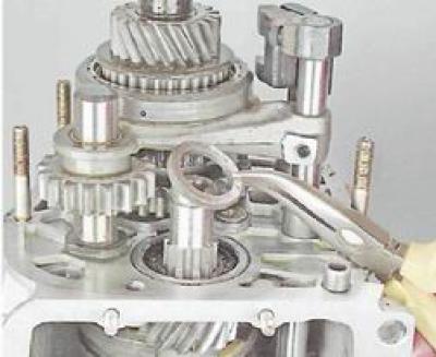
45. With a socket wrench by 13 mm we unscrew the two bolts securing the cover of the rod retainers.
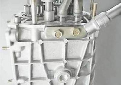
46. Remove the cover together with the gasket.
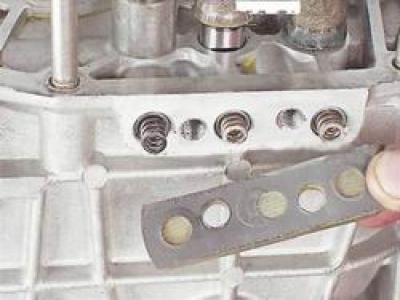
47. We remove the springs of the rod retainers from the holes in the crankcase. Spring A the V-gear and reverse gear engagement rod retainer differs from others in rigidity. To distinguish it, it has a dark color and must be installed in its place during assembly.
The text is taken from the online resource: VazBook.ru
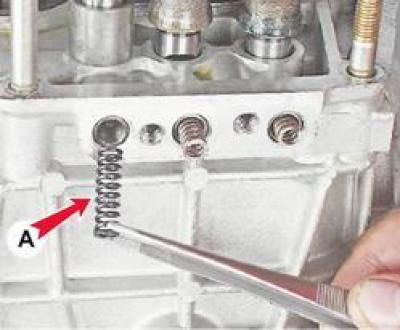
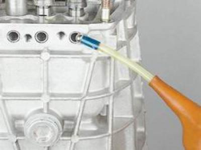
48. It is easier to remove the retaining balls using a rubber bulb, creating a vacuum.
49. Remove the V-gear gear assembly with the synchronizer from the secondary shaft.
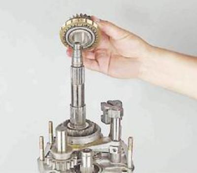
50. Remove the spacer ring.
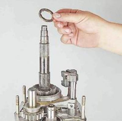
51. Having moved the gear engagement fork, we remove the 5th gear synchronizer clutch.
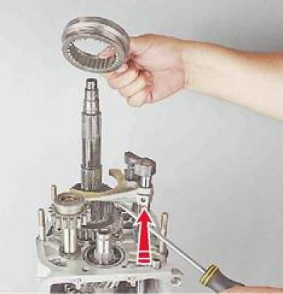
52. Holding the fork, remove the reverse intermediate gear from the axle.
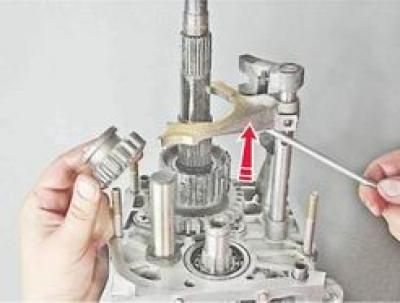
53. Remove the V-gear and reverse gear engagement rod together with the gear engagement fork and spacer sleeve A rod. Remove the bushing and fork from the rod.
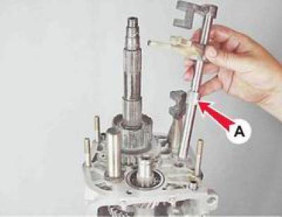
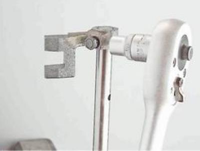
54. With a socket wrench by 10 mm we unscrew the bolt securing the rod head and remove it.
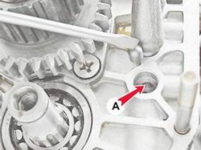
55. Using a magnetic screwdriver or a rubber bulb, remove it from the hole A there is a locking cracker in the crankcase wall.
56. Using pliers, open the retaining ring of the 5th gear synchronizer clutch hub and remove it.
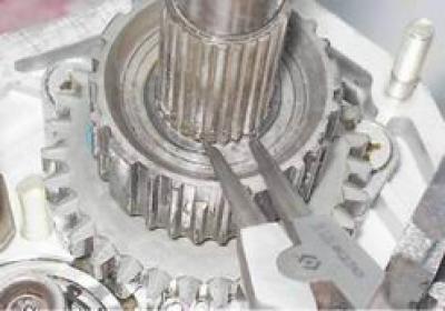
57. Remove the hub from the shaft.
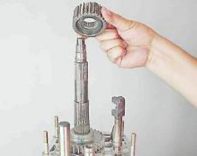
58. Remove the spring washer.
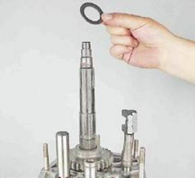
59. Remove the reverse gear.
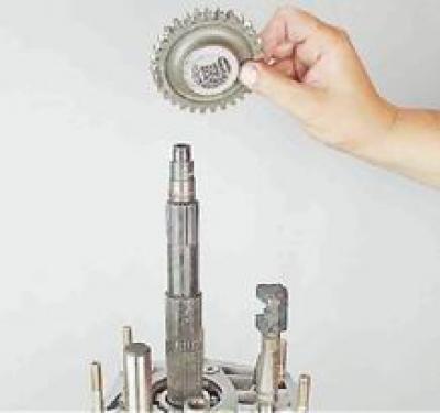
60. Pushing from the inside, we take out the rear bearing of the intermediate shaft.
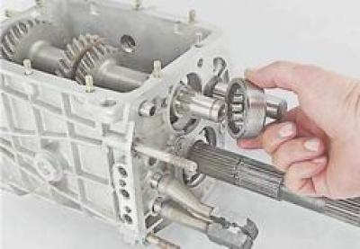
61. Using two screwdrivers, pry up the mounting ring and remove the front bearing of the intermediate shaft.
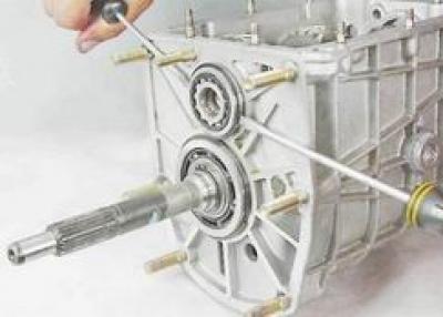
62. Remove the intermediate shaft from the crankcase.
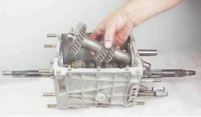
63. Using two screwdrivers, remove part of the inner ring of the rear bearing from the intermediate shaft and assemble the bearing.
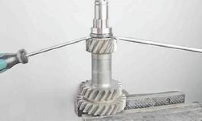
64. With a socket wrench by 10 mm using an extension, unscrew the bolt securing the fork for engaging the third and fourth gears to the rod.
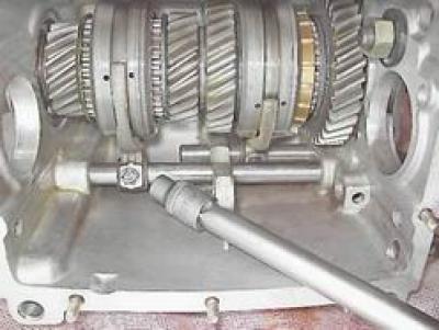
65. Remove the rod for engaging the 3rd and 4th gears from the hole, simultaneously removing the fork from it.
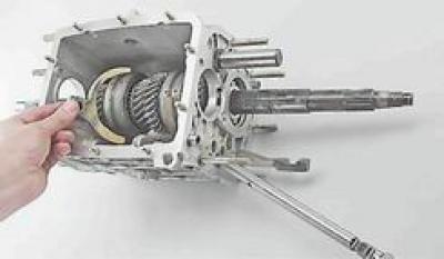
66. Remove the locking cracker from the hole in the rod.
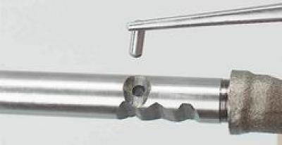
67. Using a powerful magnet or a rubber bulb, remove the locking cracker from the hole in the crankcase.
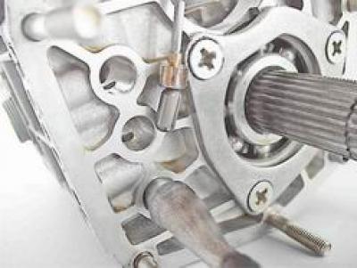
68. With a socket wrench by 10 mm we unscrew the bolt securing the fork for engaging the 1st and 2nd gears.
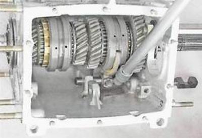
69. Remove the rod from the hole, simultaneously removing the fork from it.
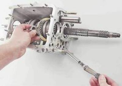
70. Using an impact screwdriver, unscrew the three screws securing the secondary shaft intermediate bearing locking plate and remove it.
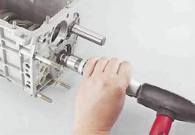
71. Using two large screwdrivers, pry the bearing mounting ring and slide the bearing out of the crankcase.
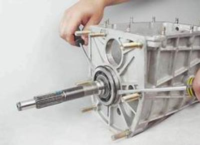
72. Remove the primary shaft assembly.
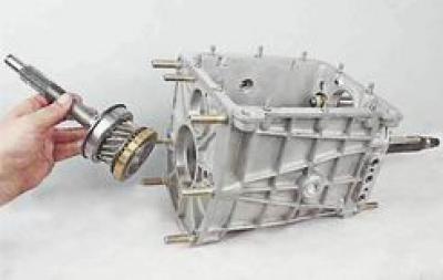
73. Remove the front roller bearing from the shaft bore. The bearing may also remain on the end of the secondary shaft.
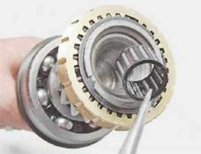
74. Using two screwdrivers, pry the installation ring of the secondary shaft intermediate bearing and pull the bearing off the shaft.
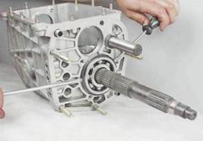
75. Remove the secondary shaft from the crankcase.
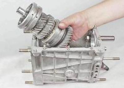
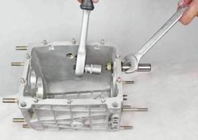
76. Holding the key by 24 mm reverse intermediate gear axle from turning, with a socket wrench by 19 mm unscrew the axle mounting nut.
77. Clamping the secondary shaft vertically in a vice using soft pads, remove the synchronization clutch of the 3rd and 4th gears from the shaft.
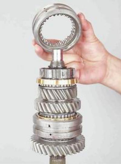
78. Using pliers, open and remove the hub retaining ring from the shaft.
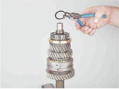
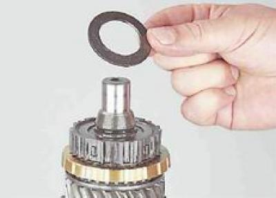
79. Remove the spring washer.
80. Remove the synchronization clutch hub.
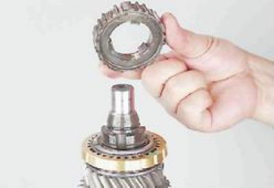
81. Remove the gear with the 3rd gear synchronizer.
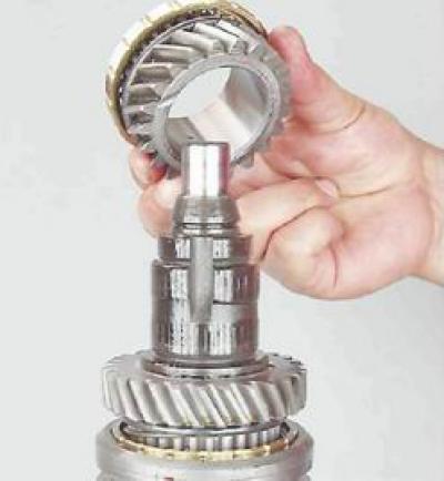
82. We support the edges of the 1st gear pinion on a rigid base (for example, two keys), thickness up to 5 mm. Using a punch made of soft metal, we press out the secondary shaft from the gear bushing.
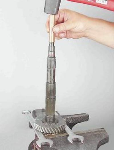
83. Remove the bushing.
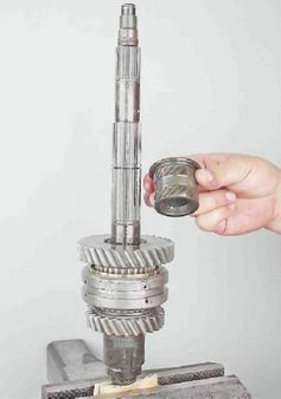
84. Remove the gear with the 1st gear synchronizer.
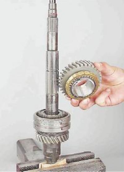
85. Remove the hub of the 1st and 2nd gear synchronization clutch.
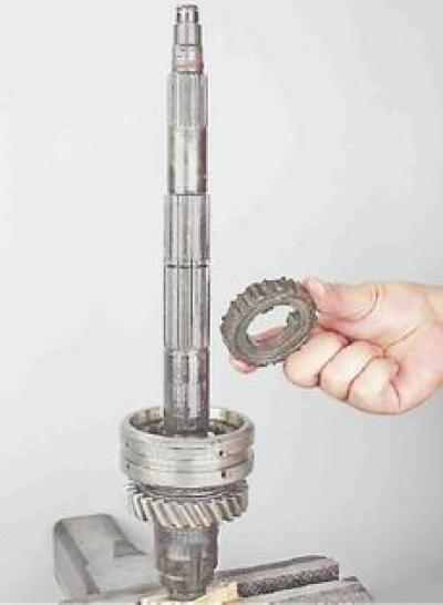
86. Remove the synchronization clutch.
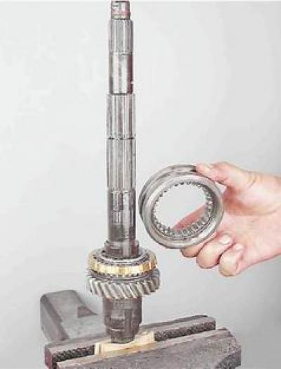
87. Remove the gear with the 2nd gear synchronizer from the shaft.
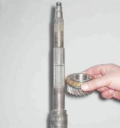
88. Having secured the primary shaft in a vice using soft pads, we use pliers to spread and remove the bearing retaining ring.
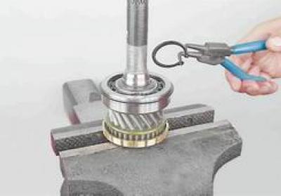
89. Remove the spring disc washer.
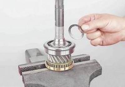
90. Resting the edges of the bearing on a rigid base, we press the primary shaft out of the inner bearing ring using a soft metal punch.
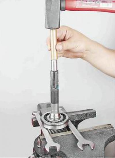
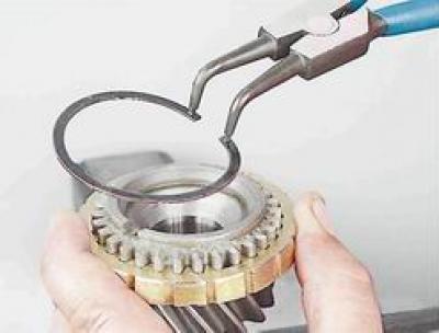
91. Holding the locking ring of the 4th gear synchronization clutch with your hand, use pliers to spread and remove the retaining ring.
92. Gradually releasing the locking ring, remove it and the 4th gear synchronizer spring.
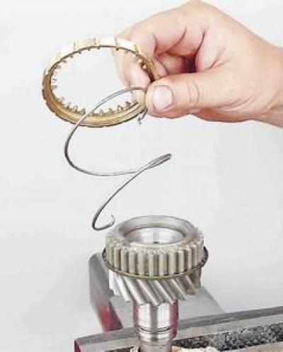
93. We analyze the synchronization mechanisms of other gears in a similar manner.
Assembly
Note: Tightening torques for critical threaded connections of parts are given in the appendices (see "Tightening torques for threaded connections").
Before assembly, wash all parts with white spirit or kerosene and blow with compressed air. Wash and blow with compressed air the bearings. Inspect and replace worn parts. There should be no damage or signs of excessive wear on the parts, and no scuff marks on the mating surfaces of the parts.
The walls of the crankcase must be free of cracks, and the bearing seats must be free of wear or damage. The contact surfaces of the gearbox housing connectors, clutch housing and rear cover must not have any damage that would cause shaft axes to diverge or insufficient sealing.
The shafts must not have any damage or excessive wear of the working surfaces and splines. Minor surface irregularities can be removed with fine-grained sandpaper; if there is significant damage or deformation, the shaft must be replaced with a new one.
Bearings should not show signs of damage to tracks, separators, balls or rollers, and when turning the bearing rings, rolling should be smooth. When repairing gearboxes with significant mileage (100 thousand km and more) it is advisable to replace all bearings with new ones, regardless of their current condition.
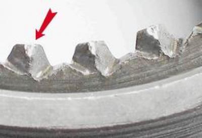
Excessive wear and chipping of gear and synchronizer teeth is not allowed; the working surface of the teeth must be smooth.
Also, deformation of the gear shift forks is not allowed; the fork rods must slide freely without significant clearance in the crankcase holes.
There should be no signs of seizing on the hubs of the gear engagement clutches.
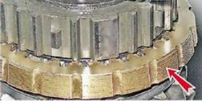
The friction surfaces of the blocking rings must have a notch. If the notch is worn out, replace the blocking ring with a new one.
1. Replace all gaskets and seals with new ones.
2. Before installation, lubricate the working surfaces of the seals with a thin layer of plastic grease.
3. When assembling the gearbox, lubricate all parts with transmission oil.
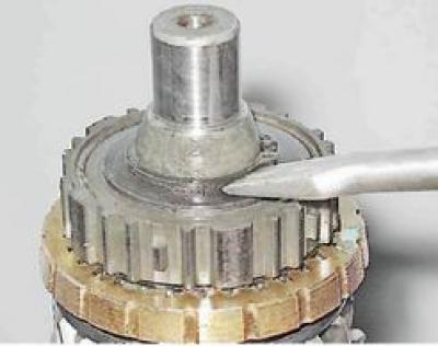
4. When assembling gear blocks on shafts, installing retaining rings, we press them with a screwdriver until the rings are completely fixed.
5. When installing bearings on shafts, apply force to the inner rings, and when installing in crankcase holes, apply force to the outer rings.
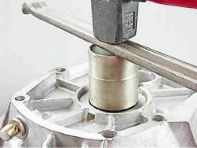
6. Using a mandrel of suitable diameter, press the primary shaft seal into the front cover.
7. Further assembly of the gearbox is carried out in the reverse order. Before installing the gearbox on the car, check the clarity of all gear engagement.