
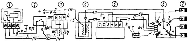
Pic. 110. Scheme of contactless ignition system:
1 - ignition relay; 2 - ignition switch; 3 - mounting block; 4 - ignition coil; 5 - switch; 6 - sensor-distributor ignition; 7 - spark plugs.
The current flowing through the primary winding of the ignition coil creates a magnetic field around the turns of the winding. At the moment of interruption of the current, the magnetic field decreases sharply and, crossing the turns of the secondary winding, induces an EMF in it of about 22... 25 kV. The high voltage current goes to the spark plugs and closes along the way: the secondary winding of the ignition coil, the high voltage wire, the central terminal of the cover, the central and outer contacts of the rotor, the side electrode of the ignition distributor sensor cover, the spark plug, «weight». Then, in parallel circuits, the current passes through the battery, generator, all consumers on, to the contacts «87» and «30» ignition relay, clamp «+B» and to the secondary winding of the ignition coil.
A high voltage applied to the center electrode of the spark plug pierces the air gap between the electrodes, and a spark jumps between them, igniting the working mixture in the engine cylinder.
To obtain maximum power and efficiency of the engine, it is necessary to ignite the working mixture a little earlier than the piston arrives at V.M.T., so that combustion ends when the crankshaft turns 10... 15°after V.M.T. In order for the fuel to burn in a timely manner, each engine speed needs its own ignition timing. With a decrease in the frequency of rotation of the crankshaft, the ignition timing should decrease, and with an increase, it should increase.
At high speed weights 1 (pic. 111) under the action of centrifugal forces, they turn about their axes, abut against the driven plate 3 and, overcoming the tension of the springs, turn it together with the screen 9 (see fig. 107) in the direction of rotation of the roller of the sensor-distributor of ignition by an angle «A» (pic. 111b). Now cut the screen to the corner «A» passes through the gap of the sensor earlier and it gives out a pulse earlier, i.e. the ignition advance increases. With a decrease in the rotational speed, the centrifugal forces decrease, and the springs turn the driven plate 3 together with the screen against the direction of rotation of the roller, i.e., the ignition advance decreases.
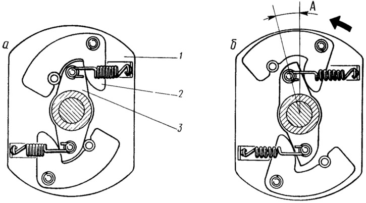
Pic. 111. Scheme of operation of the centrifugal ignition timing controller at low frequency (A) rotation of the crankshaft and at high frequency (b):
1 - leading plate of the centrifugal regulator; 2 - weights; 3 - driven plate of the centrifugal regulator.
When the load on the engine changes, the content of residual gases in the engine cylinders changes. Under heavy loads, when the carburetor throttles are fully open, the content of residual gases in the working mixture is low, so the mixture burns faster and ignition must occur later. When the engine load is reduced (throttle cover) the amount of residual gases increases, the working mixture burns longer and ignition should occur earlier. The ignition timing is adjusted by the vacuum ignition timing controller, depending on the engine load.
Aperture 20 (see fig. 107) This regulator operates under vacuum transmitted from the zone above the throttle valve of the primary chamber of the carburetor. When the throttle is closed (engine idle), the hole where the vacuum comes from is above the edge of the throttle valve, above which there is no vacuum, so the vacuum regulator does not work.
With small openings of the throttle valve, a vacuum appears in the hole area, which is transmitted to the vacuum regulator. Diaphragm 20 bends and rod 21 turns the sensor base plate against the direction of rotation of the ignition distributor shaft. The ignition advance is increased. As the throttle opens further (load increase) the vacuum decreases and the spring presses the diaphragm to its original position. The base plate of the sensor is rotated in the direction of rotation of the roller, and the ignition advance is reduced.