
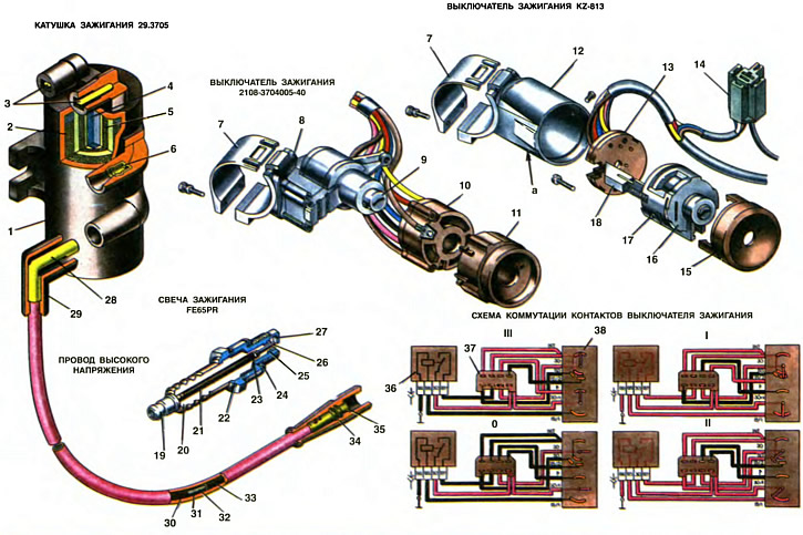
1. Body (insulating plastic). 2. Secondary winding. 3. Primary terminals (low voltage). 4. Core. 5. Primary winding. 6. Output of the secondary winding (high voltage). 7. Bracket for fastening the ignition switch. 8, 12. Ignition switch housing. 9, 16. Castle. 10, 13. Contact part. 11, 15. Facing. 14. Block for connecting the ignition relay. 17. Locking pin. 18. Locking rod of the anti-theft device. 19. Contact sleeve. 20. Insulator. 21. Contact rod. 22. Candle body. 23. Glass sealant. 24. Sealing washer. 25. Heat sink washer. 26. Central electrode. 27. Side electrode. 28. Tip for connecting to the ignition coil. 29, 34. Protective cap. 30. Outer insulating sheath. 31. Inner shell. 32. Linen cord. 33. Conductive winding. 35. Tip for attaching to the spark plug. 36. Ignition relay. 37. Connecting block. 38. Ignition switch.
a - hole for the fixing pin
On cars «Oka» High-energy non-contact ignition system is applied. She has a breaker instead (with contacts) an electronic switch is used to open the low voltage circuit, which opens and closes the circuit when the high-power output transistor is turned on and off (i.e. without contacts).
The components of the ignition system include: the ignition coil, the ignition switch, the spark moment sensor, the switch, and the high and low voltage wires. Typically, ignition systems also use an ignition distributor to alternately supply high voltage pulses to the engine cylinders. Here, there is no ignition distributor, and high voltage pulses are applied simultaneously to the spark plugs of both cylinders and twice during the engine operating cycle (two revolutions of the crankshaft). Thus, one pulse in each cylinder is working, and the second is idle.
Ignition coil
Ignition coil - brand 29.3705 high energy, with two high-voltage outputs and with an open magnetic circuit. It is attached with two nuts to the bracket on the mudguard of the left wheel.
The ignition coil has a core 4, recruited from thin plates of electrical steel. Over the core on a cardboard frame is wound primary (low voltage) winding 5 and then secondary (high voltage) winding 2. The layers of the windings are separated by insulating paper, and the windings are insulated with plastic. The ends of the primary winding are soldered to the plugs 3. and the secondary - to the sockets 6. The core with the windings is filled with plastic. The resistance of the primary winding is (0,5±0,05) Ohm, and the secondary - (11+1,5) kOhm
On cars «Oka» an interchangeable ignition coil type 3012.3705 can also be used. It is a transformer with a core made of W-shaped plates of electrical steel. The windings are filled with insulating plastic. The resistance of the primary winding of the coil 3012.3705 is (0,35±0,035) Ohm, and the secondary - (4,23±0,42) kOhm
Switch
The electronic switch is used to interrupt the current in the primary circuit of the ignition coil according to the signals of the spark moment sensor. The switch is installed in the engine compartment and fastened with two nuts to a bracket welded to the bulkhead.
On cars «Oka» switches of various brands can be used: 3620.3734, or BAT 10.2, or HIM-52, or 76.3734, or PT1903, or PZE4022, or K563.3734. All of them are interchangeable. Switches of the first two brands are assembled from individual elements - transistors, microcircuits, resistors, etc., soldered into a common circuit on a printed circuit board made of foil fiberglass. To interrupt the current, a powerful high-voltage transistor of the KT-848A type, specially designed for operation in a high-energy ignition system, is used. The printed circuit board, together with the output transistor, is placed in a die-cast aluminum case.
Switches of the BAT 10.2 and HIM-52 brands have a hybrid design, i.e. all their elements are combined in one large integrated circuit. Structurally, these switches are designed in a small rectangular plastic case, mounted on a metal plate.
The switch maintains a constant value of current pulses (scheme II, sheet 33) at the level of 8... 9 A, regardless of voltage fluctuations in the vehicle's on-board network. The switch circuit has a device for automatically reducing the duration of the current pulse in the primary winding of the ignition coil with an increase in the engine speed. In addition, automatic shutdown of the current through the ignition coil is provided when the engine is not running, but the ignition is on. After 2... 5 s after the engine stops, the output transistor of the switch is locked, without creating a spark on the spark plugs.
Ignition switch
The ignition switch is designed to turn on and off the ignition circuits, engine start and other consumers. It is mounted on the steering shaft bracket using bracket 7 and can be of two interchangeable types: 2108-3704005-40 of domestic production and KZ-813, manufactured in Hungary. The ignition switches are used together with the ignition relay type 113.3747-10, which is fixed under the instrument panel.
Structurally, switches KZ-813 and 2108-3704005-40 are made differently. The ignition switch KZ-813 has a cylindrical body 12, into which the contact part 13 and the lock 16 are inserted, connected by screws. The lock is fixed in the body with a screw and pin 17, which enters the hole a of the body. To remove the lock from the housing, it is necessary to drown the pin 17. Outside, the ignition switch is covered with a plastic lining 15.
At the ignition switch 2108-3704005-40, the lock 9 is located in the housing 8. The contact part 10 is put on the lock and fastened to the housing with a screw. Outside, the switch is also covered with a plastic lining 11.
The ignition switch key is reversible, i.e. it can be inserted into the lock in any position. Both ignition switches in the lock have a lock against restarting the starter without first turning off the ignition, i.e. it is not possible to turn the key again from position I to position II without first returning it to position 0. In addition, there is an anti-theft device. The principle of its operation is that after removing the key from the lock in position III («Parking»), the locking rod 18 extends from the housing, enters the groove of the steering shaft and blocks it.
The switching diagram shows which contacts are closed at various key positions. Voltage from power sources is supplied to the contacts «30» and «30/1», but removed from contacts «INT», «50», «15/2» and «R». Contact «15/1» (to turn on the ignition circuit) does not have a direct output to the plugs of the block 37, but only through the ignition relay 36.
Spark plug
The spark plug is designed to ignite the combustible mixture in the cylinders by a spark discharge between the electrodes. On cars «Oka» FE65PR or FE65CPR spark plugs made in Bosnia can be fitted. The difference between the FE65CPR candle is that it has a copper core in the central electrode to improve heat dissipation from the end of the electrode to the body (this is indicated by the letter C in the designation of the candle). The letter F in the designation indicates that the candle body has a M14X1.25 thread, and the second letter (E) - that the length of this thread is 19 mm. Numbers (65) characterize the glow number of the candle. The letter P means that the thermal cone (skirt) the insulator protrudes beyond the end of the case, and the letter R means that the candle has a certain internal resistance to suppress radio interference.
Similar candles of domestic production A17DVR, or A17DVRM, or A17DVRM1 can also be installed.
The design of the candles is non-separable. In the steel case 22, a ceramic insulator 20 is rolled, inside which there is a composite electrode consisting of a contact rod 21 and a central electrode 26. The side electrode 27 is welded to the case. The lower part of the rod 21 and the upper part of the central electrode are filled with a special conductive glass sealant 23 with a resistance of 4...10 kOhm. It does not allow the breakthrough of gases through the hole in the insulator and at the same time acts as a resistor to suppress radio interference. To prevent leakage of gases through the thread of the body, a sealing washer 24 made of soft iron is used, which is clamped between the body of the candle and the end surface of the socket in the cylinder head
The gap between the electrodes of the spark plug should be within 0.7... 0.8 mm. It is regulated by bending the side electrode 27. It is not allowed to adjust the gap by bending the central electrode, since the insulator skirt can be broken. During the operation of the candle, metal is transferred from the side electrode to the central one. As a result, a recess is formed on the side electrode, and a tubercle is formed on the central electrode. Therefore, it is necessary to check the gap between the electrodes of the candle not with a flat, but with a round wire probe.
The gap between the body of the spark plug and the insulator is sealed with a steel washer 25 and thermal shrinkage of the body. Thermosetting consists in heating the corbel of the body (under the hexagon) high-frequency currents up to a temperature of 700...800°C and subsequent crimping of the body with a force of 20...25 kN. Washer 25 simultaneously serves to remove heat from the insulator to the body, maintaining the temperature of the insulator skirt at a certain level.
The temperature of the insulator during engine operation mainly depends on the length of the skirt and on the thermal stress of the engine. The longer the skirt, the worse the heat dissipation from the skirt to the body and the «hotter» candle. The optimum temperature of the insulator skirt should be within 500... 600°C. If the temperature is below 500°C, i.e. the skirt is short and the candle «cold», then carbon deposits will be intensively deposited on the skirt of the insulator. If the temperature is above 600°C, then the carbon deposits will burn out, but the engine will pre-ignite the combustible mixture from a heated skirt, and not from a spark. This phenomenon is called pre-ignition. It is manifested by knocks in the engine and by the fact that after the ignition is turned off, the engine continues to work for some time.
Incandescent ignition is a harmful phenomenon. It leads to a decrease in power and to overheating of the engine, to premature wear of its main parts, and can cause cracks in the spark plug insulators and burnout of the electrodes.
To assess the ability of a candle to glow ignition, its designation contains a glow number - an abstract value proportional to the average indicator pressure in the engine cylinders at which glow ignition occurs. It is determined on special single-cylinder engines by gradually increasing the working pressure (and hence the temperature) in a cylinder. The greater the pressure in the cylinder at which glow ignition occurs, the greater the glow number, i.e., the «colder» candle.
For each engine model, the spark plug is selected individually according to the glow number. Therefore, apply on cars «Oka» any other candles than those mentioned above are not allowed.
High voltage wires
The wires transmit high voltage pulses from the coil to the spark plugs. They can be of two grades: PVVP-8 or PVPPV-40. Due to the increased thickness of the insulation, they have an outer diameter of 8 mm instead of 7 mm for the wires of a conventional ignition system.
The core of the wire is a linen fiber cord 32 enclosed in a plastic sheath 31 with a maximum addition of ferrite. On top of this shell is a conductive winding made of an alloy of iron and nickel. This wire design has a resistance distributed along the length and reduces radio and television interference. Winding resistance is 2000±200 Ohm/m for wires PVVP-8 and 2550±270 Ohm/m for wires PVPPV-40. Outside, the wire is insulated with red PVC plasticate (at wires PVVP-8) or irradiated blue polyethylene (wire PVPPV-40).
Spark torque sensor
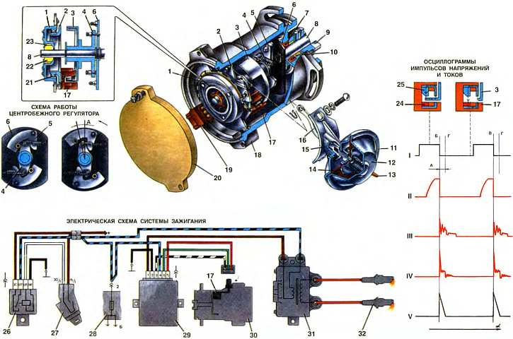
1. Front roller bearing holder
2. Sensor base plate
3. Screen
4. Driven plate of centrifugal governor
5. Weight
8. Drive plate centrifugal governor
7. Oil seal
8. Roller
9. Coupling
10. Sleeve of the rear end of the roller
11. Vacuum regulator housing
12. Vacuum regulator cover
13. Vacuum connection
14. Aperture
15. Vacuum regulator bracket
16. Pull
17. Proximity sensor
18. Body
19. Plug connector block
20. Lid
21. Bearing
22. Sleeve of the front end of the roller
23. Felt ring
24. Semiconductor plate with an integrated circuit
25. Permanent magnet
28. Ignition relay
27. Ignition switch
28. Fuse box
29. Switch
30. Spark torque sensor
31. Ignition coil
32. Spark plug
A. Ignition timing
B. The moment of ignition in the first cylinder
B. Ignition timing in the second cylinder
G. c. m.t. pistons of the first and second cylinders
I. Sensor voltage pulses
II. Current pulses at the output of the switch
III. Voltage pulses at the switch output
IV. Voltage pulses in the secondary circuit of the ignition coil
V. Current pulses in the secondary circuit of the ignition coil
a - the angle of rotation of the crankshaft of the engine
The spark torque sensor type 5520.3706 is used to issue low voltage control pulses to the switch. It contains centrifugal and vacuum ignition timing controllers and a non-contact microelectronic control pulse sensor.
Spark Torque Sensor Mounted on Auxiliary Housing (see ch. 7) and is driven directly from the rear end of the camshaft through the clutch 9. The clutch has two cams of different widths that fit into the corresponding grooves of the camshaft, which also have different widths. This ensures the exact relative position of the camshaft and roller 8. This is necessary so that the control pulses of the sensor are precisely coordinated in time with the phases of the working process in the engine cylinders (see ch. 8).
Housing 18 is cast from aluminum alloy. The roller 8 rotates in two ceramic-metal bushings 10 and 22. The bushing 10 is pressed into the housing and is lubricated with oil coming from the engine lubrication system. To prevent oil from penetrating inside the spark torque sensor, a self-clamping rubber gland 7 is installed in the housing. The bushing 22 is surrounded by a felt ring 23 soaked in oil, which is enough for the entire service life of the spark torque sensor. The axial free play of the roller 8 should be no more than 0.35 mm. It is adjusted during assembly by selecting the thickness of the washers located between the coupling and the housing, as well as between the housing and the leading plate 6 of the centrifugal regulator.
On the roller are the details of the centrifugal ignition timing controller: the leading plate 6 with two weights 5 and the driven plate 4. The leading plate is fixed on the shaft, and the driven one, together with the screen 3, is integral with the sleeve put on the shaft and fixed on it with a lock washer. Racks are attached to the driving and driven plates, for which the springs are hooked, tightening the plates. The lower end of one of the posts on the driven plate is the limiter. It fits into the groove of the drive plate and prevents the driven plate from turning more than 16.5°relative to the roller.
When the engine is running, under the action of centrifugal forces, the weights 5 diverge, with their tongues rest against the driven plate 4 and, overcoming the resistance of the springs, turn it (and hence screen 3) regarding the roller. Thus, the screen 3 is driven not directly from the roller, but through the weights and can be rotated by the weights by 16.5°relative to the roller.
There are two springs that tighten plates 4 and 8. They differ in their elasticity. The spring, which has a high elasticity, is installed with little tension and does not allow the weights to diverge at a low crankshaft speed. The centrifugal regulator comes into operation at a crankshaft speed of more than 1000 rpm, when the centrifugal force of the weights begins to overcome the resistance of this spring. At a higher speed, the second spring also comes into action (more rigid and free-standing). This ensures a given change in the ignition timing at different engine speeds.
The vacuum ignition timing controller is fixed to the housing with two screws. It consists of a housing 11 with a cover 12, between which a flexible diaphragm 14 is clamped. On the one hand, a rod 16 is attached to the diaphragm, and on the other side there is a spring that presses the diaphragm with a rod in the direction of rotation of the roller. The rod 16 is pivotally connected to the base plate 2 of the sensor. Under the action of rarefaction, the diaphragm bends and, through the rod, rotates plate 2 together with the contactless sensor clockwise, i.e., against the direction of rotation of the roller. The base plate 2 of the sensor is mounted on a ball bearing 21 pressed into the holder 1.
The contactless sensor 17 is fixed with screws on the plate 2. The principle of its operation is based on the use of the Hall effect. It consists in the occurrence of a transverse electric field in a semiconductor plate with current under the action of a magnetic field on it. The sensor consists of a semiconductor plate with an integrated circuit 24 and a permanent magnet 25 with a radio tape recorder. There is a gap between the plate and the magnet, in which there is a steel screen 3 with two slots.
When the screen body passes through the sensor gap (see picture), then the magnetic lines of force close through the screen and do not act on the plate. Therefore, there is no potential difference in the plate. If there is a screen slot in the gap, then a magnetic field acts on the semiconductor plate and the potential difference is removed from it.
An integrated circuit built into the sensor converts the potential difference that occurs on the plate into voltage pulses of negative polarity. Thus, when the screen body is in the gap of the sensor, then there is a voltage at its output, approximately 3 V less than the supply voltage. If a screen slot passes through the sensor gap, then the voltage at the sensor output is close to zero (no more than 0.4 V).
Operation of the ignition system
After the ignition is switched on, the contacts are closed «30» and «87» relay 26 ignition. Through them, the battery supplies voltage to one of the low-voltage terminals of the ignition coil 31, to the plug «4» switch 29 and from its plug «5» further to the proximity sensor 17.
When the crankshaft of the engine is rotated by the starter, the screen 3 rotates and the sensor 17 outputs rectangular pulses I to the plug «6» a switch that converts them into pulses II current in the primary winding of the ignition coil. The current first gradually increases to a value of 8... 9 A. and then abruptly interrupted by the sensor signal. Current interruption moment (corresponding to the moment of sparking) determined by the transition of the sensor pulse from high to low. In this case, the amplitude of voltage pulses III at the output transistor of the switch at the moment of interruption of the current reaches 350... 400 V. The duration of the current pulses depends on the speed of the crankshaft. With a supply voltage of 14 V, it decreases from about 8 ms at 750 rpm to 4 ms at 1500 rpm.
The current flowing in the primary winding of the ignition coil creates a magnetic field around the turns of the winding. At the moment of interruption of the current, the magnetic field is sharply compressed and, crossing the turns of the secondary winding, induces an EMF in it of the order of 22... 25 kV. The high voltage current closes along the path: the upper high-voltage output of the coil 31 - the spark plug of the first cylinder - ground - the spark plug of the second cylinder - the lower high-voltage output of the ignition coil. In this case, a spark discharge occurs simultaneously at two spark plugs: the first and second cylinders. In one of the cylinders, the compression stroke ends at this time and the discharge ignites the combustible mixture, and in the other cylinder, the exhaust gases are released at this time and the discharge occurs idly.
The combustible mixture burns out in about thousandths of a second. During this time, the engine crankshaft rotates 20... 50° (depending on speed). To obtain maximum power and efficiency of the engine, it is necessary to ignite the combustible mixture a little earlier than the arrival of the piston in c. m.t., so that combustion ends when the crankshaft is rotated 10... 15°after c. m.t., i.e., the spark discharge must be created with the necessary advance.
With excessively early ignition, when the ignition timing is too large, the combustible mixture burns out before the piston arrives in c. m.t. and slows it down. As a result, engine power is reduced, knocks occur, the engine overheats and runs unsteadily at low idling speed. With late ignition, the combustible mixture will burn out when the piston goes down, i.e. in conditions of increasing volume. In this case, the gas pressure will be significantly lower than during normal ignition, and engine power will also decrease. In addition, the mixture in the exhaust pipe may burn out.
In order for the combustion of fuel to occur in a timely manner, each engine speed needs its own ignition timing. Elementary (installation) ignition timing is 1°±1° (4°±1°for motors 11113) at a crankshaft speed of 820... 900 rpm. With an increase in the frequency of rotation, the ignition timing should increase, and with a decrease in frequency, it should decrease. This task is performed by a centrifugal ignition timing controller.
With an increase in the rotational speed of the roller, the weights 5 rotate about their axes under the action of centrifugal forces. The tongues of the weights rest against the driven plate 4 and, overcoming the tension of the springs, turn it together with the screen 3 in the direction of rotation of the roller by angle A. Now the slot of the screen passes earlier (at corner A) through the gap of the sensor, and it gives out a pulse earlier, i.e., the ignition advance increases. With a decrease in the rotational speed, the centrifugal forces decrease, and the springs turn the driven plate 4 together with the screen against the direction of rotation of the roller, i.e., the ignition advance decreases.
When the load on the engine changes, the content of residual gases in the engine cylinders changes. At heavy loads, when the carburetor throttles are fully open, the content of residual gases in the mixture is low, the mixture is rich and burns faster, and ignition should occur later. When the engine load is reduced (throttle cover) the amount of residual gases increases, the working mixture becomes leaner and burns longer, so ignition must occur earlier. The ignition timing is adjusted by the ignition advance vacuum regulator depending on the engine load.
The diaphragm 14 of this regulator is affected by a vacuum transmitted from the zone above the throttle valve of the primary chamber of the carburetor. When the throttle is closed (engine idle), the hole through which the vacuum is transmitted to the regulator is above the edge of the throttle valve and the vacuum regulator does not work.
With small openings of the throttle valve, a vacuum appears in the hole area, which is transmitted to the vacuum regulator. The diaphragm 14 is retracted and the rod 16 rotates the base plate 2 of the sensor against the direction of rotation of the roller. The ignition advance is increased. As the throttle opens further (load increase) the vacuum decreases, and the spring presses the diaphragm to its original position. The base plate of the sensor is rotated in the direction of rotation of the roller, and the ignition advance is reduced.