




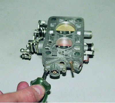
Using a Phillips screwdriver, unscrew the two screws securing the bushing..
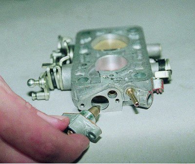
…and remove it together with the mixture quantity adjustment screw.
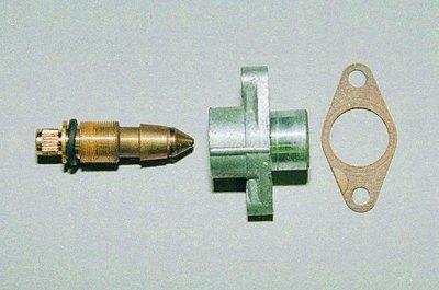
We remove the gasket from the bushing and unscrew the screw, counting the number of its turns. Having removed the sealing ring from the screw, we wash it in acetone and blow it with compressed air.
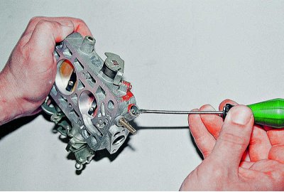
Using a thin screwdriver, tighten the quality screw until it stops, recording the number of turns made, and then completely unscrew the screw..
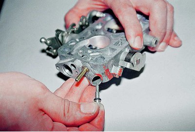
…and take it out. Having removed the rubber sealing ring, wash the screw in acetone and blow it with compressed air.
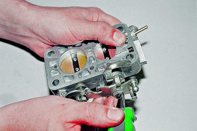
Using a screwdriver, loosen the nut of the first chamber throttle valve axis.
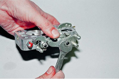
Using an 11 mm wrench, unscrew the nut.
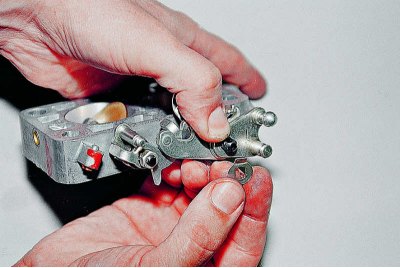
We remove the locking plate,...
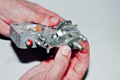
... throttle actuator lever,...
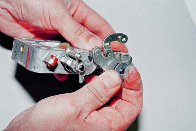
…a puck,...
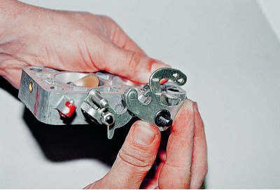
...the lever that limits the opening of the second chamber throttle valve,...
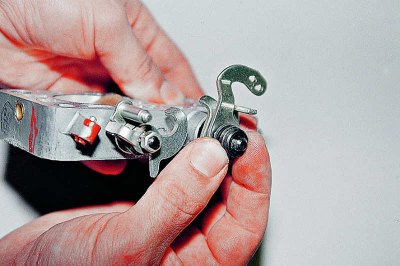
…a bushing,...
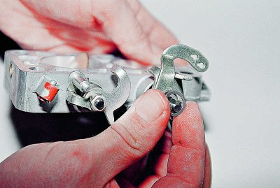
…a spring washer,...
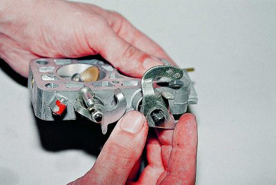
…the lever connecting to the air damper,...
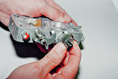
…a puck,...
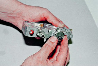
…throttle lever stop,...
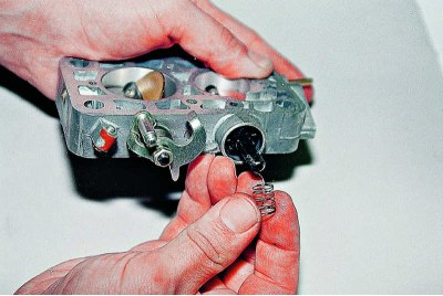
…spring…
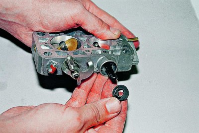
…and the valve of the engine crankcase ventilation system. Remember the position in which it is installed on the axle so that it can be installed correctly during assembly.
We thoroughly wash the valve core and the throttle body in acetone or solvent, then blow out the body channels with compressed air.
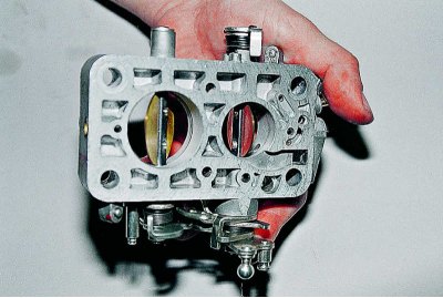
Having opened the flaps, we check the condition of the transition holes, if necessary, we clean them with thin copper wire.
We assemble the throttle body in the reverse order of disassembly, paying special attention to the correct position of the levers on the axis.
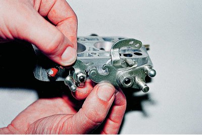
Before tightening the nut, make sure that the limiter lever is located below the protrusion of the second chamber throttle lever.
We screw the quality screw into place until it stops (after wetting its rubber ring with motor oil) and unscrew it, making the number of turns recorded during disassembly.
We turn the quantity screw by the previously calculated number of turns.
For reliable operation of the idle system, the throttle valves must close their channels tightly, without a gap. A barely noticeable gap is allowed, which can only be seen when looking at the light. Sometimes it is possible to eliminate the gap by changing the position of the valve in the slot of the axis. But this is usually done as a last resort. The carburetor of a new car, as a rule, does not need such adjustment.
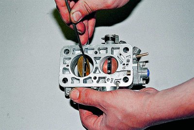
Having slightly opened the flap, we file down the threaded part of the screws - during assembly they are countered by crushing the thread. New screws will be required for assembly.
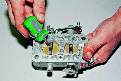
Using a Phillips screwdriver, unscrew the two screws and replace them with new ones.
We loosen the stop screw of the damper lever. By changing the position of the damper, we achieve the smallest gap along its entire perimeter.
For better adhesion of the damper to the walls, you can grind it from the end. It is better to grind it with a small flat file. We determine the boundaries of the excess metal by light, marking them with a pencil.
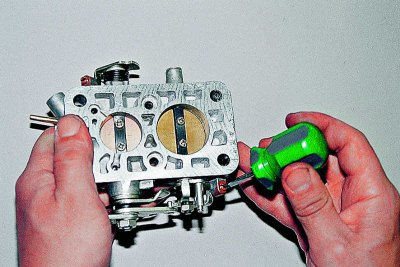
Before assembly, make sure that the flaps are not jammed (this is especially important for the second camera) – if necessary, we adjust them with a stop screw, and we counter-attach the new shutter mounting screws by riveting the threads.
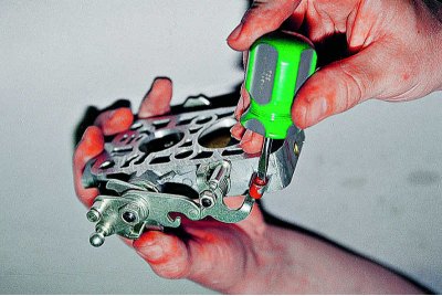
We lock the stop screws by loosening their slot.
When assembling the carburetor, we replace damaged and deformed gaskets.
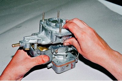
When installing the cover on the carburetor body, make sure that the float does not touch the walls of the float chamber.
When tightening the cover mounting screws, do not apply excessive force to avoid deformation.
Having installed the carburetor on the engine, we check the idle speed, if necessary, adjust it with the quantity screw. We also recommend checking the concentration of CO-CH in the exhaust gases.