




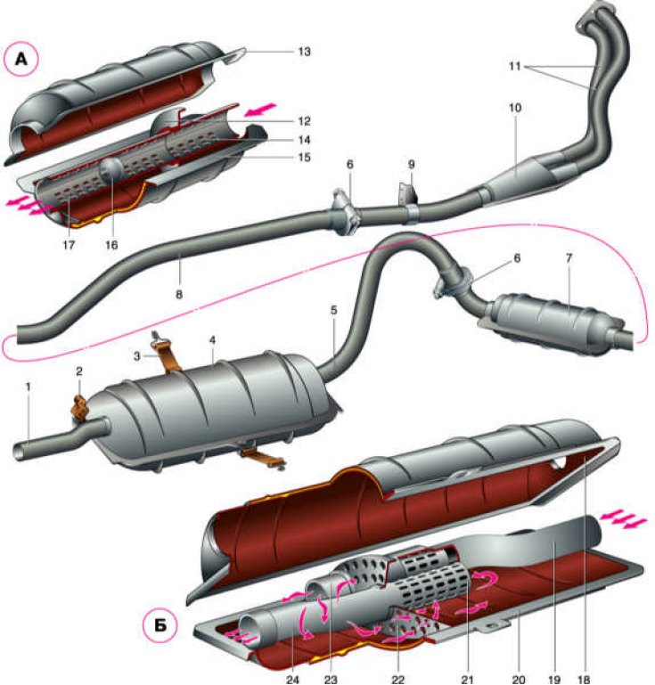
1 – exhaust pipe; 2 – exhaust pipe suspension cushion; 3 – muffler suspension belt; 4 – main muffler; 5 – front pipe of the main muffler; 6 – clamps; 7 – additional muffler; 8 – front pipe of additional muffler; 9 – clamp for fastening the inlet pipe to the gearbox; 10 – gas receiver; 11 – intake pipes; 12 – blind partition; 13 – upper half-body of additional muffler; 14 – front perforated pipe; 15 – lower half-body of the additional muffler; 16 – diaphragm; 17 – rear perforated pipe; 18 – upper half-body of the main muffler; 19 – inlet pipe; 20 – lower half-body of the main muffler; 21 – perforation on pipes for gas energy dissipation; 22 – perforated partition; 23 – left pipe; 24 – outlet pipe;
A, B – diagrams of the passage of exhaust gases through the additional and main mufflers, respectively.
The exhaust system consists of three separate sections. The exhaust gases from the exhaust manifold enter the intake pipe, then pass through the additional and main mufflers and exit into the atmosphere. The muffler pipes are connected to each other with clamps.
The intake pipe flange is secured with four brass nuts to the manifold studs through a reinforced asbestos gasket.
The main muffler is attached to the bottom of the trunk with two rubber straps and a rubber pad. The mufflers are non-disassemblable and cannot be repaired.
(The article is taken from an online resource VAZbook.ru)