




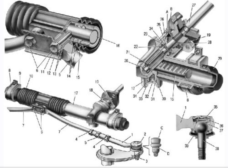
7.1. Steering gear assembly with drive: 1 – steering rod end; 2 – ball joint of the tip; 3 – rotary lever; 4 – lock nut; 5 – traction; 6 – bolts for fastening the steering rods to the rack; 7 – inner tie rod ends; 8 – steering gear mounting bracket; 9 – steering gear support; 10 – protective cover; 11 – locking plate; 12 – connecting plate; 13 – rubber-metal hinge; 14 – damping rings; 15 – rack support sleeve; 16 – rack; 17 – steering gear housing; 18 – tension bolt; 19 – elastic coupling flange; 20 – roller bearing; 21 – drive gear; 22 – ball bearing; 23 – retaining ring; 24 – protective washer; 25 – sealing ring; 26 – bearing nut; 27 – intermediate steering shaft; 28 – boot; 29 – protective cap; 30 – stop sealing ring; 31 – rack stop; 32 – spring; 33 – stop nut; 34 – retaining ring of the stop nut; 35 – plug; 36 – liner spring; 37 – ball joint insert; 38 – ball pin; 39 – protective cap; A, B – marks on the dust cover and crankcase; C, D – surfaces on the ball joint and the pivot arm
Steering gear assembled with steering rods, it is attached to the front shield of the body in the engine compartment on two brackets using clamps 8 (Fig. 7.1). The mechanism is secured with nuts on welded bolts through rubber supports (cushions) 9.
In the housing 17 of the steering gear, a drive pinion 21 is mounted on a roller 20 and a ball 22 bearing, which is engaged with the rack 16. The inner race of the ball bearing is fixed on the shaft of the pinion by a retaining ring 23, and the outer race is pressed by a nut 26 to the end face of the bearing seat in the housing of the steering gear. A sealing ring 25 is located in the groove of the nut. A protective washer 24 is installed between the nut and the retaining ring 23. The nut is locked in the housing by a washer and covered by a boot 28 put on the shaft of the drive pinion. Marks A and B are made on the boot and the housing of the steering gear for setting the steering gear rack to the middle position. Rack 16 is pressed against the teeth of the drive gear by spring 32 through metal-ceramic stop 31, sealed in the crankcase by rubber ring 30. The spring is pressed by nut 33 with locking ring 34, which creates resistance to unscrewing the nut.
A protective cap 29 is put on the steering gear housing on the left side, and a pipe with a longitudinal groove is pressed on the right side. The spacer bushings of the rubber-metal hinges 13 of the inner ends 7 of the steering rods pass through the groove of the pipe and the holes in the protective cover 10. The steering gear rods are attached to the rack with bolts 6, which pass through the connecting plate 12 and the spacer bushings of the rubber-metal hinges 13. The bolts are fixed with a locking plate 11.
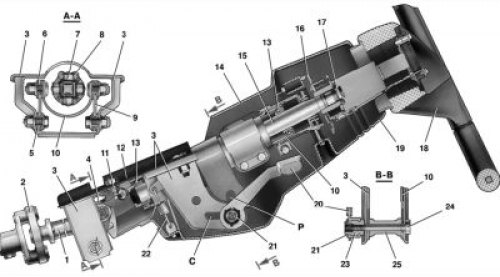
7.2. Steering column: 1 – intermediate steering shaft; 2 – coupling sleeve; 3 – steering shaft mounting bracket; 4 – cardan joint; 5 – spacer sleeve; 6 – support plate bushing; 7 – universal joint crosspiece; 8 – crosspiece needle bearing; 9 – support plate; 10 – steering shaft bracket pipe; 11 – fixing plate; 12 – welded body bracket; 13 – steering shaft bearing; 14 – upper part of the facing casing; 15 – upper steering shaft; 16 – contact plate holder; 17 – steering wheel mounting nut; 18 – steering wheel; 19 – lower part of the facing casing; 20 – steering column adjustment lever; 21 – retaining ring; 22 – release spring; 23 – lever adjusting sleeve; 24 – tension bolt; 25 – spacer sleeve
The source is on the website www.VAZbook.ru
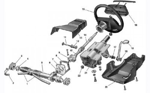
7.3. Steering components: 1 – inner tie rod ends; 2 – steering gear mounting bracket; 3 – steering gear support; 4 – spacer ring; 5 – steering mechanism; 6 – sealing gasket; 7 – seal thrust plate; 8 – seal; 9 – lower flange of the elastic coupling; 10 – intermediate steering shaft; 11 – tension bolt; 12 – spacer sleeve; 13 – facing casing (upper part); 14 – upper steering shaft; 15 – steering wheel; 16 – signal switch cover; 17 – adjusting sleeve; 18 – steering column adjustment lever; 19 – retaining ring; 20 – facing casing (lower part); 21 – Steering shaft mounting bracket; 22 – steering shaft bearing
The steering shaft consists of an upper 15 (Fig. 7.2) and an intermediate 1 shaft, connected to each other by a cardan joint 4. The intermediate shaft is connected to the drive gear by a flange 9 (Fig. 7.3) through an elastic coupling. The upper shaft is installed in a pipe 10 (see fig. 7.2) bracket 3 on two ball bearings 13 with elastic bushings on the inner ring.
The bracket 3 for fastening the steering shaft is attached to the welded bracket 12 of the body at four points, wherein the front part of the bracket is secured through two fixing plates 11 with bolts with breakaway heads. The rear part of the bracket 3 of the steering shaft is secured on the welded bolts with nuts with spring washers or self-locking nuts without spring washers. The bracket 3 for fastening the steering shaft and its pipe 10 are connected to each other pivotally by two plates 9 using four bolts with plastic 6 and metal 5 bushings. With such a connection, the pipe together with the upper steering shaft can move both in the angular and axial directions relative to bracket 3. The angular movement occurs by the value of the slot P in the angular adjustment guide plate welded to the pipe, and the axial movement occurs by the value of the slot C in the axial adjustment guide of bracket 3. Thus, it is possible to change the angle of the steering column and move it along the axis within the length of the slots C and P.
The lever 20 for adjusting the position of the steering column is used to fix the pipe 10 relative to the bracket 3. Splines are cut in its hub, by means of which it is connected to the adjusting sleeve 23 and fixed on its splines by a locking ring 21. The sleeve 23 is screwed onto the tie bolt 24, which passes through the slots of the guide plates of the pipe 10 and the bracket 3. A spacer sleeve 25 is installed on the bolt. A rectangular projection is made under the head of the bolt 24 or a welded part with projections is installed, as a result of which the bolt is fixed from turning. When the lever 20 is turned downwards, the compression force of the guide plates decreases, which allows you to manually change the angle of the steering column. After installing the steering column in the required position in the axial direction, the tie bolt on the gear shaft is tightened, and the adjusting lever 20 is raised upward, and the column is fixed in the installed position.
Springs 22 of bracket 3 of the steering shaft fastening pull the bracket tube to the upper position, preventing the tube from freely moving downwards when lever 20 is in the lower position. The steering drive consists of two composite steering rods and pivot levers 3 (see fig. 7.1) telescopic struts of the front suspension. The length of each rod is changed by tubular rod 5, which is screwed onto rod ends 7 and 1 and secured with nuts 4. The ball joint parts are located in the head of the outer rod end: insert 37, pin 38 and spring 36. Pivot lever 3 is welded to the body of the telescopic strut of the front suspension.