
English Русский
Български
Беларускі
Український
Српски
Hrvatski
Română
Polski
Slovenský
Magyar
| Articles | Contacts | Sitemap |   
Repair and maintenance Lada Repair and maintenance Mazda Repair and maintenance Mitsubishi Repair and maintenance Toyota Repair and maintenance Land Rover Repair and maintenance Hyundai Repair and maintenance Nissan
VAZbook.ru


Main     1111   2101   2105   2106   2107   2109   2110   2115   2121  
VAZ-2114 (2004-2013) VAZ-2115 (1997-2012)
  • Main
  • «Samara-2»
  • VAZ-2115
  • Transmission
  • Car gearbox
  • Secondary shaft repair

Secondary shaft repair (VAZ-2115)

            0

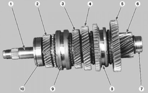
Secondary shaft of the gearbox: 1 – secondary shaft; 2 – 4th gear pinion; 3 – gear of the 3rd gear;…

Secondary shaft of the gearbox: 1 – secondary shaft; 2 – 4th gear pinion; 3 – gear of the 3rd gear; 4 – 2nd gear pinion; 5 – 1st gear pinion; 6 – main gear drive pinion; 7 – inner ring of the front shaft bearing; 8 – synchronizer of 1st and 2nd gears with reverse gear ring gear; 9 – synchronizer of III and IV gears; 10 – rear shaft bearing


1. Using a little force, clamp the shaft in a vice with soft metal jaws.
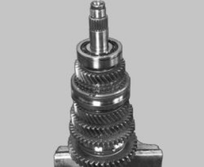
Warning! The secondary shaft must be clamped in a vice with soft pads on the jaws by the inner race…


Warning! The secondary shaft must be clamped in a vice with soft pads on the jaws by the inner race of the front bearing. Tighten the vice so that the shaft can be tilted by hand, otherwise the surface of the bearing race may be damaged.


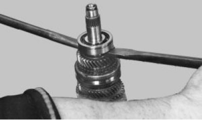
2. Using two mounting blades, press out the secondary shaft rear bearing.


3. Remove the thrust washer…


The original can be seen on the website www.VazBook.ru

3. Remove the thrust washer…
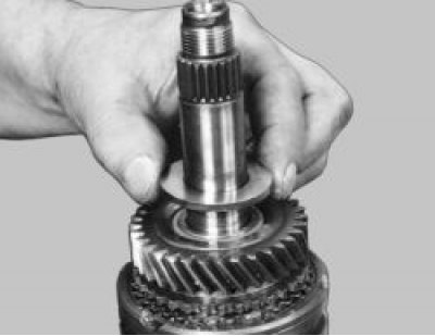
4. …driven gear of the 4th gear…
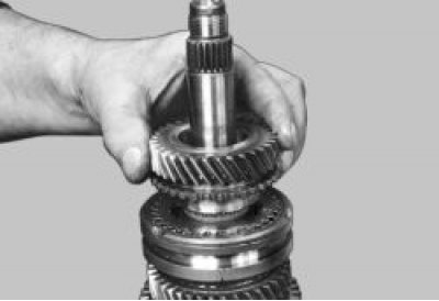

4. …driven gear of the 4th gear…

5. …the needle bearing of the fourth gear pinion and mark it.
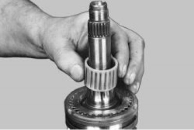

5. …the needle bearing of the fourth gear pinion and mark it.

Warning! Be sure to mark the needle bearings and bushings according to the gear number. When…


Warning! Be sure to mark the needle bearings and bushings according to the gear number. When assembling, they must be installed in the same places. The most convenient way is to insert the corresponding needle bearing into the gear and (where is it) bushing…
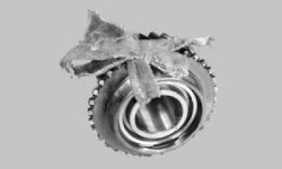


…and tie them with rope or wire.


…and tie them with rope or wire.


6. Remove the spacer ring.
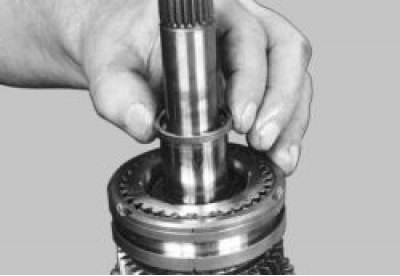
7. Using two mounting blades, move the synchronizer of III and IV gears from the shaft splines…


7. Using two mounting blades, move the synchronizer of III and IV gears from the shaft splines through the III gear pinion.
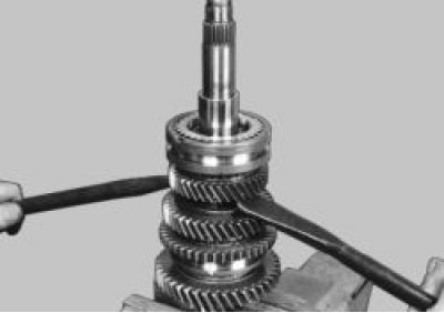
8. Remove the 4th gear needle bearing bushing.
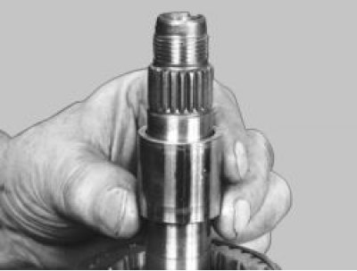

8. Remove the 4th gear needle bearing bushing.

9. Remove the synchronizer of III and IV gears with the IV gear locking ring.
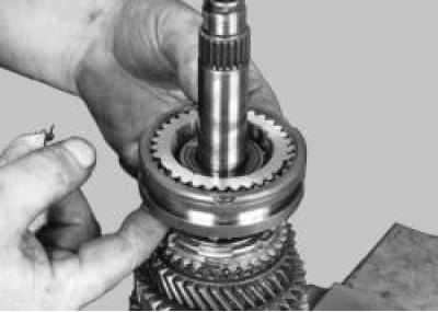

9. Remove the synchronizer of III and IV gears with the IV gear locking ring.

10. Mark the locking ring relative to the synchronizer sleeve.


10. Mark the locking ring relative to the synchronizer sleeve.

Warnings!

Be sure to mark the locking rings relative to the coupling. During operation, the teeth of the rings are worn to the teeth of the coupling, so during assembly, the rings must be installed in the same position.

If you do not plan to disassemble the synchronizer, tie it with rope or wire so that it does not fall apart.


11. Remove the third gear locking ring and mark it relative to the synchronizer clutch.
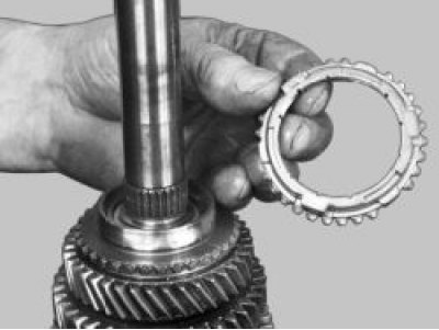
12. Remove the 3rd gear.
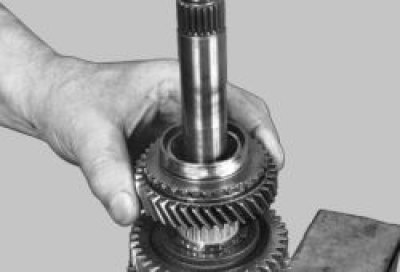

12. Remove the 3rd gear.

13. Remove the needle bearing of the 3rd gear pinion and mark it.
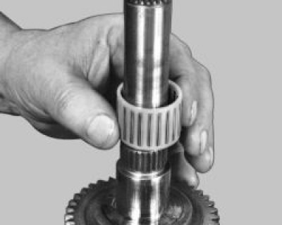

13. Remove the needle bearing of the 3rd gear pinion and mark it.

14. Remove the retaining ring of the thrust half rings…
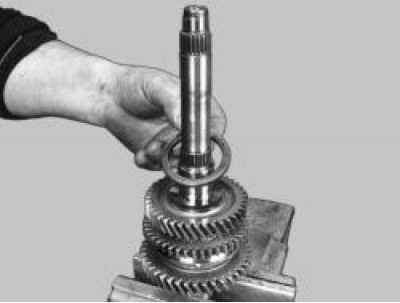

14. Remove the retaining ring of the thrust half rings…

15. …and two thrust half rings.
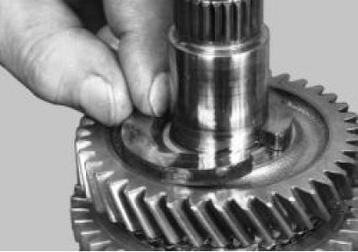

15. …and two thrust half rings.

16. Remove the locking ball from the hole on the shaft.
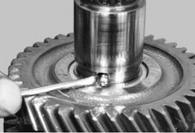

16. Remove the locking ball from the hole on the shaft.

17. Remove the 2nd gear.
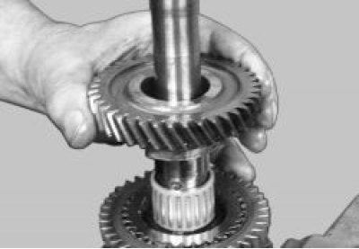

17. Remove the 2nd gear.

18. Remove the needle bearing of the 2nd gear and mark it.
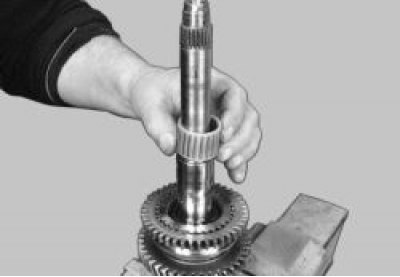

18. Remove the needle bearing of the 2nd gear and mark it.

19. Remove the snap ring.
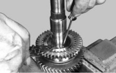

19. Remove the snap ring.

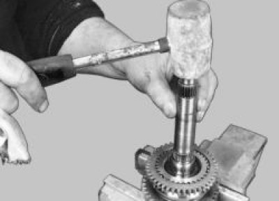
20. Place the 1st gear shaft on the jaws of a vice and, using a wooden mallet on the end of the…


20. Place the 1st gear shaft on the jaws of a vice and, using a wooden mallet on the end of the shaft, press the synchronizer of 1st and 2nd gears off the shaft splines.
21. Remove the synchronizer of the 1st and 2nd gears with the 2nd gear locking ring.
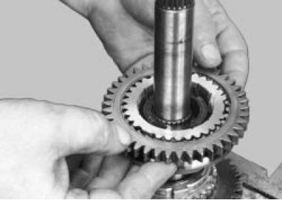

21. Remove the synchronizer of the 1st and 2nd gears with the 2nd gear locking ring.

Note.


Note.

The reverse gear ring gear is made on the synchronizer of the first and second gears.


22. Remove the 1st gear locking ring and mark it relative to the synchronizer clutch.
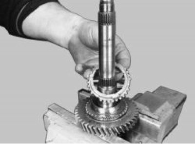
23. Remove the 1st gear.
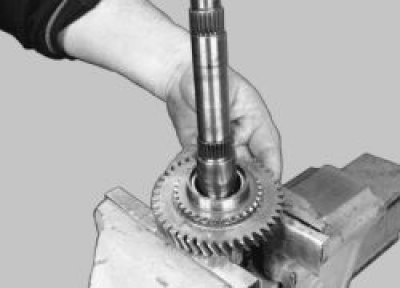

23. Remove the 1st gear.

24. Remove the retaining ring.
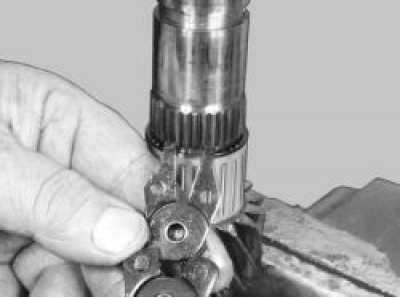

24. Remove the retaining ring.

25. Slightly loosen the 1st gear needle bearing lock and remove the bearing by sliding it along the…


25. Slightly loosen the 1st gear needle bearing lock and remove the bearing by sliding it along the shaft. Mark the bearing.
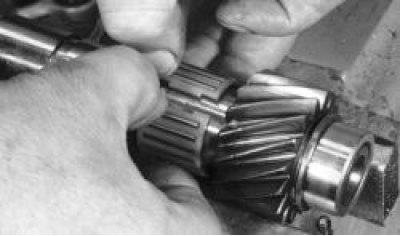
26. Turn the shaft over and use two large screwdrivers to press out the inner race of the front…


26. Turn the shaft over and use two large screwdrivers to press out the inner race of the front shaft bearing. Then remove the thrust washer.
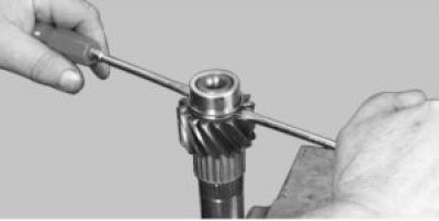
27. Thoroughly clean, wash and dry the secondary shaft parts. Inspect them carefully.


27. Thoroughly clean, wash and dry the secondary shaft parts. Inspect them carefully.

28. Check the condition of the shafts. If there is pitting (cavities) on the bearing journals or signs of wear, the shafts must be replaced. The shaft splines must not have dents, burrs or signs of wear. Replace shafts with defective splines.
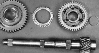
29. Check the condition of the gearbox gears. If there are chips, chipped teeth, scoring in the…


29. Check the condition of the gearbox gears. If there are chips, chipped teeth, scoring in the internal holes and other damage, the gears must be replaced.
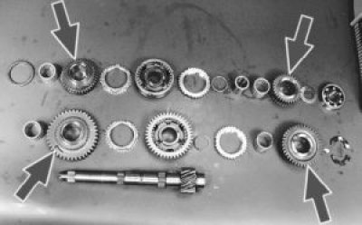
30. Check the condition of the bearings. If there is pitting (cavities) on the raceways and rolling…


30. Check the condition of the bearings. If there is pitting (cavities) on the raceways and rolling elements, traces of indentation of the rolling elements on the raceways, or damage to the separators, replace the bearings.
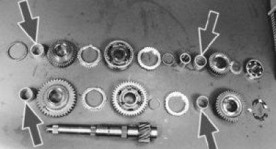
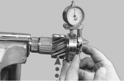
31. The radial clearance of ball and roller bearings should not exceed 0.05 mm. This can be checked…


31. The radial clearance of ball and roller bearings should not exceed 0.05 mm. This can be checked with an indicator. Mount the bearing on the shaft and the indicator leg on the top point of the outer ring of the bearing. Lightly press the bearing from the bottom up. The difference in the indicator readings between the initial position and when pressing on the bearing will be the radial clearance.
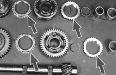
32. Check the condition of the synchronizer locking rings. If there are nicks and chips on the…


32. Check the condition of the synchronizer locking rings. If there are nicks and chips on the toothed rims or significant wear on the cones, replace the locking rings.
33. Check the clearance between the gears and their corresponding locking rings. The minimum…


33. Check the clearance between the gears and their corresponding locking rings. The minimum allowable clearance is 0.6 mm. If it is less, the locking ring must be replaced.
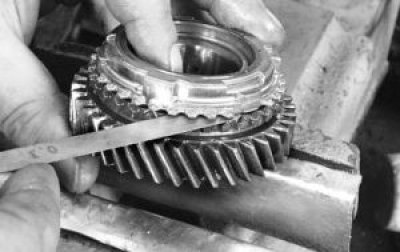
Note: When replacing the locking ring, check the clearance between the new ring and the gear. Check…


Note: When replacing the locking ring, check the clearance between the new ring and the gear. Check the correct conical surface of the ring by placing it on the cone of the gear and rocking it by hand; backlash is unacceptable.


34. If you find scoring or deformation on the thrust washers and retaining rings, or if the retaining rings lose elasticity, replace them.
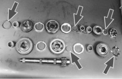
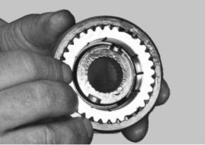
35. Assemble the secondary shaft in the reverse order of disassembly. Install the old blocking…


35. Assemble the secondary shaft in the reverse order of disassembly. Install the old blocking rings in accordance with the marks made earlier. Install the new rings so that the small protrusions on the ring (missing teeth) coincided with the grooves of the synchronizer hub where the locks are installed.
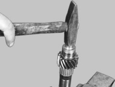
36. Press the rear shaft bearing in using a suitable mandrel, applying force only to the inner ring…


36. Press the rear shaft bearing in using a suitable mandrel, applying force only to the inner ring of the bearing.
37. After assembly, check the operation of the synchronizers. To do this, manually move the…


37. After assembly, check the operation of the synchronizers. To do this, manually move the synchronizer clutches to the position of engaging the corresponding gears.
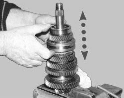
37. After assembly, check the operation of the synchronizers. To do this, manually move the…


This article is available at russian, bulgarian, belarusian, ukrainian, serbian, croatian, romanian, polish, slovak, hungarian
The text was reviewed by the specialist: Grigory Vologodtsev

Share with friends:

Previous articles
VAZ-2115: Car gearbox
Next articles

Gearbox disassembly and defect detection
Removal and installation the gearbox
Possible gearbox malfunctions
Gearbox design features
Primary shaft repair
Synchronizer repair
Differential repair
Selecting the differential bearing adjusting ring
Gear selection mechanism repair

More articles from other manuals on VAZ cars:
➠ Secondary shaft repair VAZ-11113 (1996-2003)
➠ Secondary shaft seal — replacement VAZ-2104 (1984-2012)
➠ Secondary shaft seal — replacement VAZ-2106 (1976-2006)
➠ Secondary shaft seal — replacement VAZ-2107 (1982-2012)
➠ Secondary shaft of the gearbox — design description VAZ-21099 (1990-2004)
Link in different formats to this page


Visitor comments

No comments yet


How much will 28 + 42 ?


VAZ-2114 (2004-2013) 
  • General information
  • Operation and maintenance
  • Power unit
  • Engine repair
  • Cooling system
  • Supply system
  • Control system
  • Exhaust system
  • Transmission
  • Clutch
  • Car gearbox
  • Front wheel drives
  • Chassis
  • Wheels and tires
  • Front suspension
  • Rear suspension
  • Steering
  • Brake system
  • Body
  • Exterior
  • Interior
  • Doors and glass
  • Tailgate
  • Ventilation and heating
  • Electrical equipment
  • Equipment and devices
  • Headlights and lighting
  • Engine electrics
  • Electrical circuits


VAZ-2115 (1997-2012) 
  • General information
  • Vehicle device
  • Operation manual
  • Vehicle malfunctions
  • Car care
  • Power unit
  • Engine repair
  • Cooling system
  • Supply system
  • Control system
  • Exhaust system
  • Transmission
  • Clutch
  • Car gearbox
  • Front wheel drives
  • Chassis
  • Front suspension
  • Rear suspension
  • Steering
  • Brake system
  • Body
  • Exterior
  • Interior
  • Doors, covers and windows
  • Electrical equipment
  • Equipment and devices
  • Headlights and lighting
  • Engine electrics
  • Anti-theft system


VAZbook.ru © 2017 · Mobile version · Contact with administration · Sitemap: EN BG BY UA RS HR RO PL SK HU · Site search · News and articles VAZ-1111 · VAZ-11113 · VAZ-2101 · VAZ-21011 · VAZ-2104 · VAZ-2105 · VAZ-21051 · VAZ-2106 · VAZ-21061 · VAZ-2107 · VAZ-21099 · VAZ-2109 · VAZ-2108 · VAZ-2110 · VAZ-2112 · VAZ-2114 · VAZ-2115 · VAZ-2121 · VAZ-21213 · VAZ-21214 ·
The site stores technical data using cookies to improve the service.