
English Русский
Български
Беларускі
Український
Српски
Hrvatski
Română
Polski
Slovenský
Magyar
| Articles | Contacts | Sitemap |   
Repair and maintenance Lada Repair and maintenance Mazda Repair and maintenance Mitsubishi Repair and maintenance Toyota Repair and maintenance Land Rover Repair and maintenance Hyundai Repair and maintenance Nissan
VAZbook.ru


Main     1111   2101   2105   2106   2107   2109   2110   2115   2121  
VAZ-2114 (2004-2013) VAZ-2115 (1997-2012)
  • Main
  • «Samara-2»
  • VAZ-2115
  • Transmission
  • Car gearbox
  • Gearbox disassembly and defect detection

Gearbox disassembly and defect detection (VAZ-2115)

            0

Warning! If during the gearbox repair process at least one of the following parts was replaced: clutch or gearbox housings, differential housing or differential bearings, then it is necessary to select a differential bearing adjusting ring.


You will need: wrenches "10", "12", "13", "17", socket heads "10", "13", "17", screwdriver, pliers.

1. Remove the gearbox from the vehicle (see "Removal and installation the gearbox"). Clean it from dirt and wash the outside.

2. Install the gearbox vertically upwards. Unscrew the six nuts securing the rear cover.
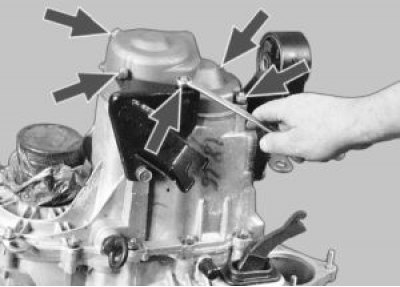
3. Unscrew the mounting bolt and remove the clutch cable bracket.
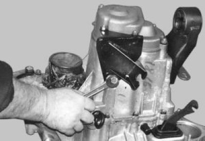

3. Unscrew the mounting bolt and remove the clutch cable bracket.

4. Carefully knock the back cover off using a rubber hammer.
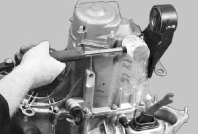

4. Carefully knock the back cover off using a rubber hammer.

5. Remove the rear cover from the gearbox housing…
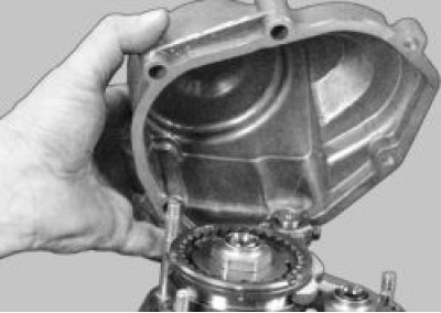

5. Remove the rear cover from the gearbox housing…


6. …and the lid sealing gasket.
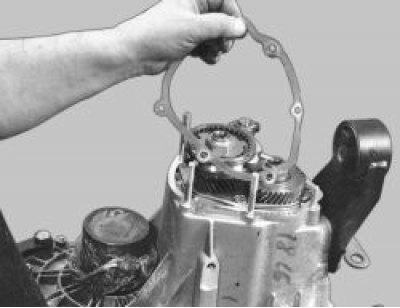

6. …and the lid sealing gasket.

Warning: Remove the sealing gasket carefully, as an undamaged gasket can be reinstalled during…


Warning: Remove the sealing gasket carefully, as an undamaged gasket can be reinstalled during assembly.


7. Engage III or IV gear.
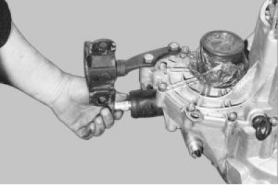
8. Loosen the 5th gear fork mounting bolt and engage 5th gear by moving the synchronizer sleeve…


8. Loosen the 5th gear fork mounting bolt and engage 5th gear by moving the synchronizer sleeve down together with the fork so that the sleeve splines engage with the gear.
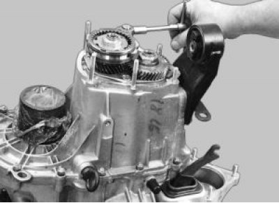

9. Make sure that the shafts do not turn.
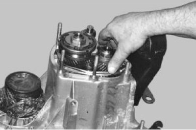

9. Make sure that the shafts do not turn.

10. Unlock and unscrew the nuts on the secondary…
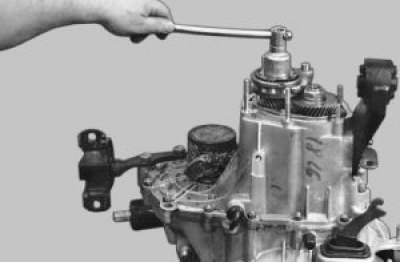

10. Unlock and unscrew the nuts on the secondary…

11. …and the primary shafts.
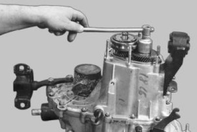

11. …and the primary shafts.

12. Use screwdrivers to pry up the 5th gear synchronizer by the hub…
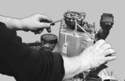

12. Use screwdrivers to pry up the 5th gear synchronizer by the hub…

13. …and remove it together with the fork. Remove the fork from the coupling.
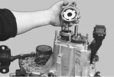

13. …and remove it together with the fork. Remove the fork from the coupling.

Warning! Remove the synchronizer carefully. Make sure that the synchronizer sleeve does not come…


Warning! Remove the synchronizer carefully. Make sure that the synchronizer sleeve does not come off the hub - the spring-loaded locking balls of the synchronizer may fall apart.


14. Remove the 5th gear synchronizer locking ring.
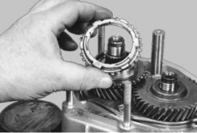
15. Use a screwdriver to pry up the driven gear of the 5th gear…
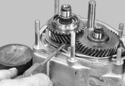

15. Use a screwdriver to pry up the driven gear of the 5th gear…

16. …and remove it from the secondary shaft.
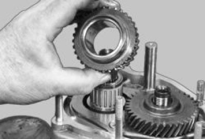

16. …and remove it from the secondary shaft.

17. Remove the needle bearing thrust ring.
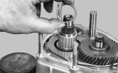

17. Remove the needle bearing thrust ring.

18. Remove the 5th gear needle bearing.
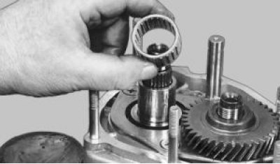

18. Remove the 5th gear needle bearing.

19. Use a screwdriver to pry up the V-gear drive gear…
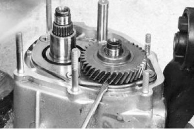

19. Use a screwdriver to pry up the V-gear drive gear…

20. …and remove it from the input shaft.
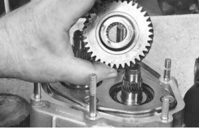

20. …and remove it from the input shaft.

21. Using an impact screwdriver, remove the four bearing plate mounting screws…
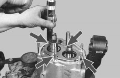

21. Using an impact screwdriver, remove the four bearing plate mounting screws…

22. …and remove the plate.
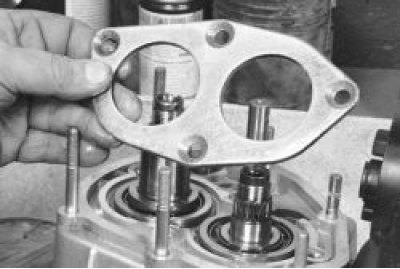

22. …and remove the plate.

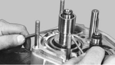
23. Use screwdrivers to pry up and remove the 5th gear needle bearing sleeve from the secondary…


23. Use screwdrivers to pry up and remove the 5th gear needle bearing sleeve from the secondary shaft.
24. Remove the thrust washer from the secondary shaft.
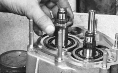

24. Remove the thrust washer from the secondary shaft.

25. Remove the primary shaft bearing retaining ring. To do this, press the retaining ring against…


25. Remove the primary shaft bearing retaining ring. To do this, press the retaining ring against the bearing ring with one screwdriver, and use the other screwdriver to remove the ring from the groove.
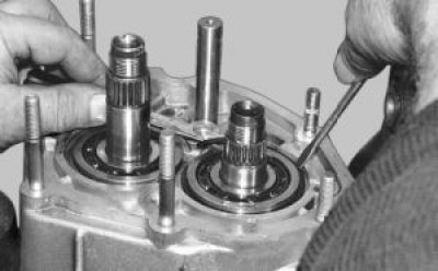
26. Remove the secondary shaft bearing retaining ring in the same manner.
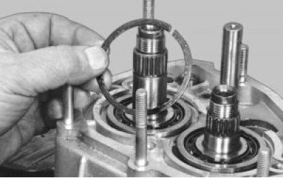

26. Remove the secondary shaft bearing retaining ring in the same manner.

27. Unscrew the retainer plug.
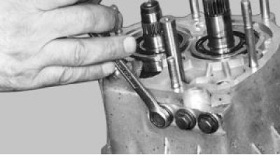

27. Unscrew the retainer plug.

28. Carefully remove the retainer ball with the spring. Remove the other two retainers in the same…


28. Carefully remove the retainer ball with the spring. Remove the other two retainers in the same manner.
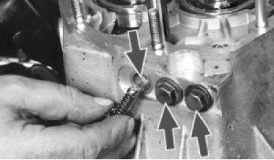
29. Remove the two mounting bolts…
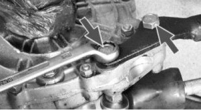

29. Remove the two mounting bolts…

30. …and remove the rear support of the power unit.
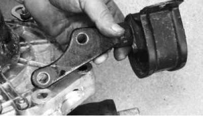

30. …and remove the rear support of the power unit.

31. Unscrew the plug of the reverse lock. Tilt the box and remove the lock ball with the spring.
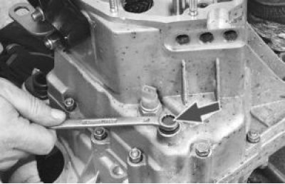

31. Unscrew the plug of the reverse lock. Tilt the box and remove the lock ball with the spring.

32. Unscrew the twelve nuts and remove the bolt securing the gearbox housing to the clutch housing.
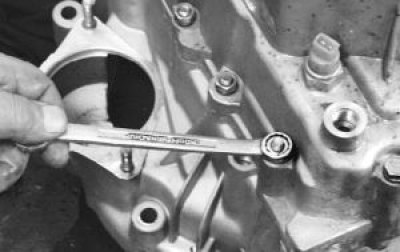

32. Unscrew the twelve nuts and remove the bolt securing the gearbox housing to the clutch housing.

33. Using a large screwdriver, carefully separate the clutch and gearbox housings.
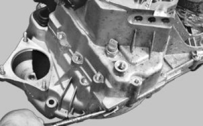

33. Using a large screwdriver, carefully separate the clutch and gearbox housings.

Note: There are three places between the housings where you can insert a screwdriver without…


Note: There are three places between the housings where you can insert a screwdriver without damaging the sealing gasket. Alternately insert the screwdriver into these slots and gently rock until the housings separate.


34. Remove the gearbox housing.
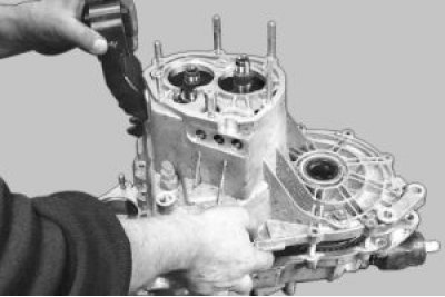
35. Unscrew the bolt securing the 1st and 2nd gear shift fork.
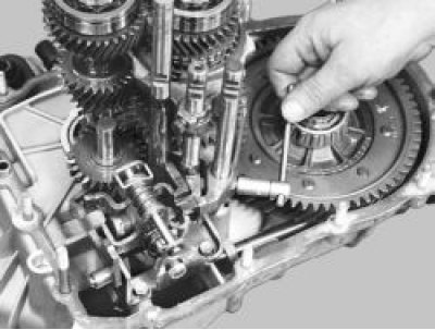

35. Unscrew the bolt securing the 1st and 2nd gear shift fork.

36. Lift the rod and remove it together with the 1st and 2nd gear shift fork.
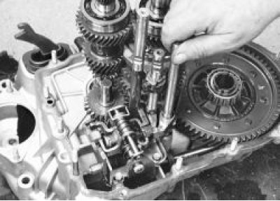

36. Lift the rod and remove it together with the 1st and 2nd gear shift fork.

37. Unscrew the bolt securing the shift fork for III and IV gears.
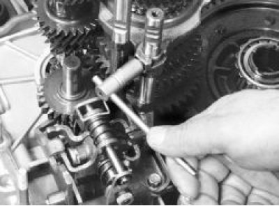

37. Unscrew the bolt securing the shift fork for III and IV gears.

38. Disengage the rod head from engagement with the lever…


38. Disengage the rod head from engagement with the lever…

39. …and remove it together with the fork.
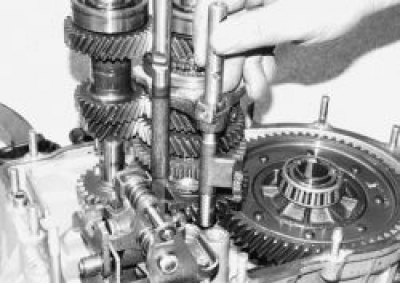

39. …and remove it together with the fork.

40. Turn the V-gear fork rod, removing its head from the lever. Remove the rod.


40. Turn the V-gear fork rod, removing its head from the lever. Remove the rod.

41. Remove the retaining ring.
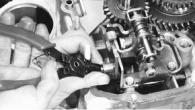

41. Remove the retaining ring.

42. Remove the reverse gear fork.
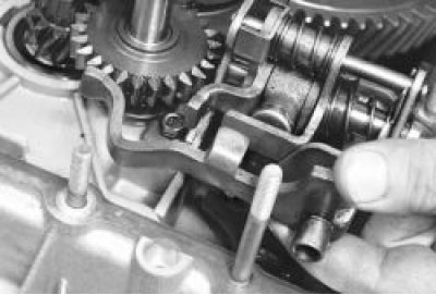

42. Remove the reverse gear fork.

43. Remove the reverse gear with the axle.
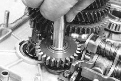

43. Remove the reverse gear with the axle.

44. While rocking slightly, remove the primary and secondary shafts simultaneously.
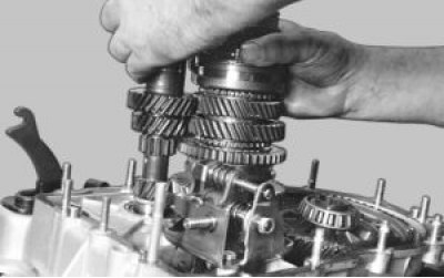

44. While rocking slightly, remove the primary and secondary shafts simultaneously.

Note: When both transmission shafts are removed, the front bearing inner races remain on the shafts.


Note: When both transmission shafts are removed, the front bearing inner races remain on the shafts.


45. Remove the final drive driven gear together with the differential.
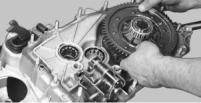
46. Remove the three mounting bolts…
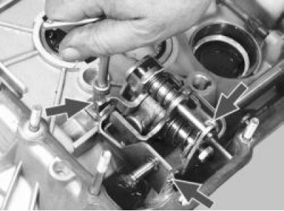

46. Remove the three mounting bolts…

47. …and remove the gear shift mechanism.
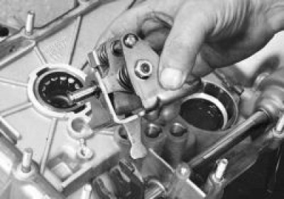

47. …and remove the gear shift mechanism.

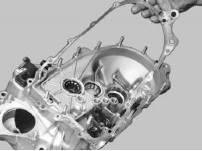
48. Carefully remove the sealing gasket.

(The original can be seen on the website: VAZBOOK.ru)

48. Carefully remove the sealing gasket.

Helpful Hint: Do not damage the sealing gasket when removing it. An undamaged gasket can be reused…


Helpful Hint: Do not damage the sealing gasket when removing it. An undamaged gasket can be reused when assembling the gearbox.


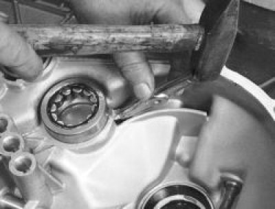
49. Press the front bearing of the secondary shaft out of the clutch housing. You can use a puller paw or similar tool for this.
50. To replace the front bearing of the input shaft, press out the oil seal.
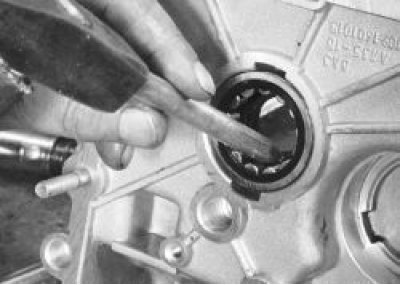

50. To replace the front bearing of the input shaft, press out the oil seal.

Warnings! Only press out the front input shaft bearings and seal when replacing them or replacing…


Warnings! Only press out the front input shaft bearings and seal when replacing them or replacing the clutch housing. It is impossible to press out the input shaft seal without damaging it. Therefore, when replacing the input shaft bearing, you will need a new seal.


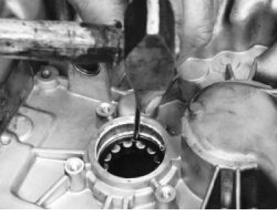
51. Press the bearing into the crankcase, applying force to the outer ring of the bearing.
52. Remove the magnet from the clutch housing.
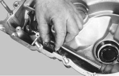

52. Remove the magnet from the clutch housing.

53. Unscrew the nut securing the speed sensor drive housing.
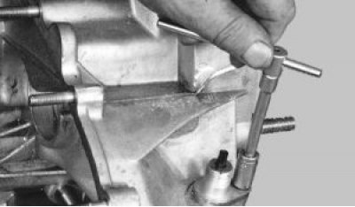

53. Unscrew the nut securing the speed sensor drive housing.

54. Use a screwdriver to pry up the housing…
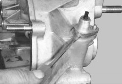

54. Use a screwdriver to pry up the housing…

55. …and remove the housing with the driven gear of the sensor drive.
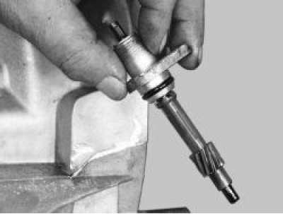

55. …and remove the housing with the driven gear of the sensor drive.

Note: If during operation traces of oil leakage through the hole for the speed sensor drive are…


Note: If during operation traces of oil leakage through the hole for the speed sensor drive are noticed, replace the rubber sealing ring on the drive housing.


56. Remove the driven gear with the sensor drive shaft from the housing.
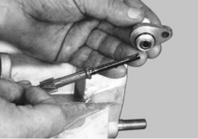
57. Push the sealing ring out of the drive housing.
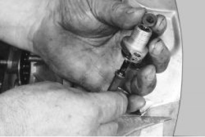

57. Push the sealing ring out of the drive housing.

58. Unscrew the reverse light switch from the gearbox housing.
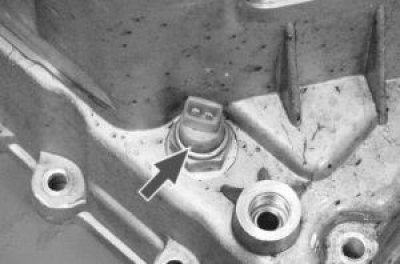

58. Unscrew the reverse light switch from the gearbox housing.

59. Slide the gearshift rod joint protective boot off the flange on the gearbox.
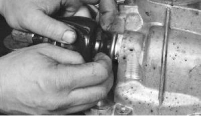

59. Slide the gearshift rod joint protective boot off the flange on the gearbox.

60. Remove the opposite edge of the protective cover from the hinge flange.
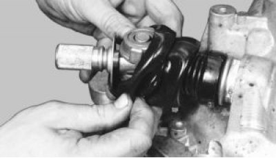

60. Remove the opposite edge of the protective cover from the hinge flange.

61. Unscrew the bolt securing the hinge to the rod…
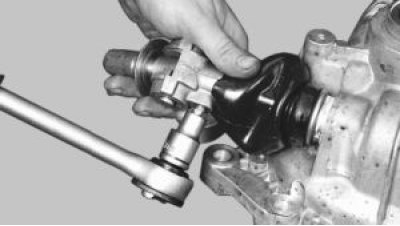

61. Unscrew the bolt securing the hinge to the rod…

62. …remove the hinge from the rod…
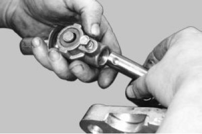

62. …remove the hinge from the rod…

63. …and a protective case.
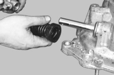

63. …and a protective case.

64. Remove the bolt securing the lever to the gearshift rod inside the clutch housing.
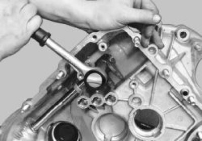

64. Remove the bolt securing the lever to the gearshift rod inside the clutch housing.

65. Remove the lever and rod from the clutch housing.
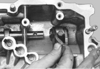

65. Remove the lever and rod from the clutch housing.

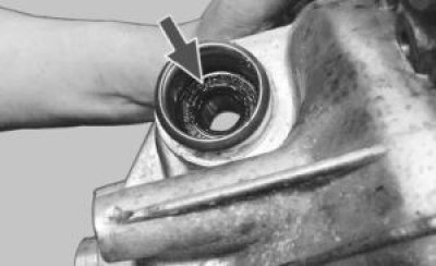
66. If during operation traces of oil leakage were noticed through the hole in the clutch housing…


66. If during operation traces of oil leakage were noticed through the hole in the clutch housing under the gearshift rod, replace the rod seal.
Before inspection and defect detection, thoroughly wash and dry the gearbox parts.


Before inspection and defect detection, thoroughly wash and dry the gearbox parts.

67. Inspect the clutch and gearbox housings, as well as the rear cover. They should not have any cracks or chips. The mating surfaces should not have any nicks, scratches, dents, etc. Remove minor damage with sandpaper. In case of severe damage, replace the defective parts.
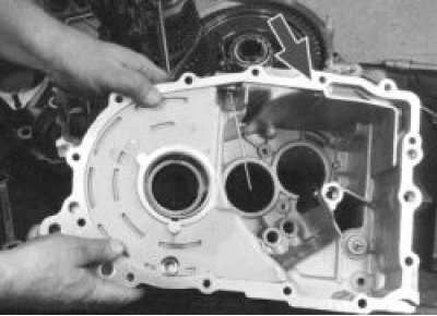
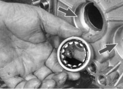
68. Check the bearing seats in both crankcases. These surfaces should not show any signs of wear or…


68. Check the bearing seats in both crankcases. These surfaces should not show any signs of wear or damage. If there is damage, replace the crankcases.
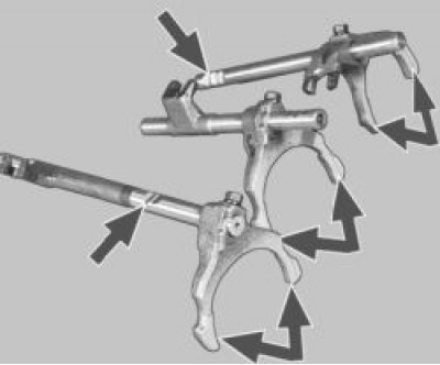
69. Check the condition of the gear shift rods. If they are bent or the rods have burrs, nicks, or…


69. Check the condition of the gear shift rods. If they are bent or the rods have burrs, nicks, or wear on the dimples for the locking pins, replace the rods. Check the condition of the gear shift forks. If the forks are bent or the tabs are worn, replace these parts.
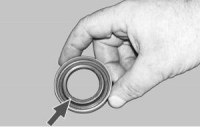
70. If oil leaks through the seals are detected during operation and the working edges are worn,…


70. If oil leaks through the seals are detected during operation and the working edges are worn, the seals must be replaced.
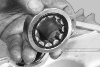
71. Check the condition of the bearings. If there is pitting (cavities) on the raceways and rolling…


71. Check the condition of the bearings. If there is pitting (cavities) on the raceways and rolling elements, traces of indentation of the rolling elements on the raceways, or if the separators are damaged, the bearings must be replaced.
72. Replace damaged or heavily compressed gaskets.
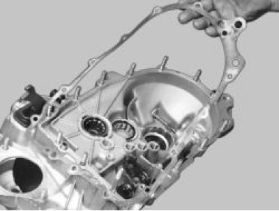

72. Replace damaged or heavily compressed gaskets.

73. Clean the magnet from wear particles. If the magnet has cracks or its magnetic properties have…


73. Clean the magnet from wear particles. If the magnet has cracks or its magnetic properties have weakened, replace the magnet.

74. Carefully clean the mating surfaces of the clutch and gearbox housings and the rear cover from old sealant.

Assemble the gearbox in the reverse order of disassembly, taking into account the following.

75. Before installing the shafts, engage the teeth of their gears and install them in the clutch housing in this position.
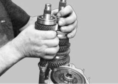
Please note how the forks should be installed on the gear shift rods:


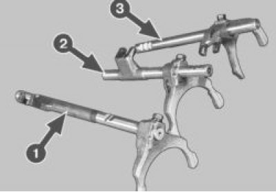
Please note how the forks should be installed on the gear shift rods:
  • 1 – rod with fork for engaging V gear;
  • 2 – rod with fork for engaging III and IV gears;
  • 3 – rod with fork for engaging 1st and 2nd gears.
77. Generously lubricate all rubbing parts with transmission oil.


77. Generously lubricate all rubbing parts with transmission oil.

78. Don't forget to put the magnet back in place.


This article is available at russian, bulgarian, belarusian, ukrainian, serbian, croatian, romanian, polish, slovak, hungarian
The text was reviewed by the specialist: Grigory Vologodtsev

Share with friends:

Previous articles
VAZ-2115: Car gearbox
Next articles

Removal and installation the gearbox
Possible gearbox malfunctions
Gearbox design features
Secondary shaft repair
Primary shaft repair
Synchronizer repair
Differential repair
Selecting the differential bearing adjusting ring

More articles from other manuals on VAZ cars:
➠ Inspection and defect detection of gearbox parts VAZ-21099 (1990-2004)
➠ Engine parts defect detection VAZ-11113 (1996-2003)
➠ Gearbox device VAZ-2101 (1970-1983)
➠ The device of a four-speed gearbox VAZ-2105 (1979-2010)
➠ The device of the four-speed gearbox VAZ-2106 and VAZ-2103 VAZ-2106 (1976-2006)
Link in different formats to this page


Visitor comments

No comments yet


How much will 23 + 29 ?


VAZ-2114 (2004-2013) 
  • General information
  • Operation and maintenance
  • Power unit
  • Engine repair
  • Cooling system
  • Supply system
  • Control system
  • Exhaust system
  • Transmission
  • Clutch
  • Car gearbox
  • Front wheel drives
  • Chassis
  • Wheels and tires
  • Front suspension
  • Rear suspension
  • Steering
  • Brake system
  • Body
  • Exterior
  • Interior
  • Doors and glass
  • Tailgate
  • Ventilation and heating
  • Electrical equipment
  • Equipment and devices
  • Headlights and lighting
  • Engine electrics
  • Electrical circuits


VAZ-2115 (1997-2012) 
  • General information
  • Vehicle device
  • Operation manual
  • Vehicle malfunctions
  • Car care
  • Power unit
  • Engine repair
  • Cooling system
  • Supply system
  • Control system
  • Exhaust system
  • Transmission
  • Clutch
  • Car gearbox
  • Front wheel drives
  • Chassis
  • Front suspension
  • Rear suspension
  • Steering
  • Brake system
  • Body
  • Exterior
  • Interior
  • Doors, covers and windows
  • Electrical equipment
  • Equipment and devices
  • Headlights and lighting
  • Engine electrics
  • Anti-theft system


VAZbook.ru © 2017 · Mobile version · Contact with administration · Sitemap: EN BG BY UA RS HR RO PL SK HU · Site search · News and articles VAZ-1111 · VAZ-11113 · VAZ-2101 · VAZ-21011 · VAZ-2104 · VAZ-2105 · VAZ-21051 · VAZ-2106 · VAZ-21061 · VAZ-2107 · VAZ-21099 · VAZ-2109 · VAZ-2108 · VAZ-2110 · VAZ-2112 · VAZ-2114 · VAZ-2115 · VAZ-2121 · VAZ-21213 · VAZ-21214 ·
The site stores technical data using cookies to improve the service.