
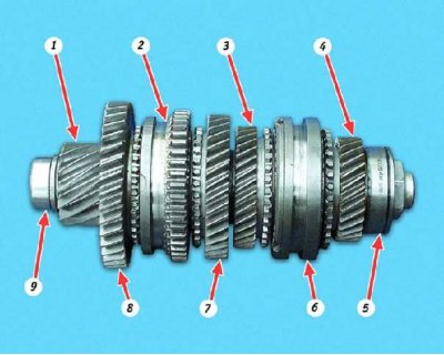
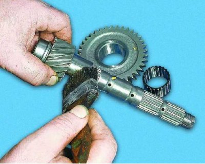
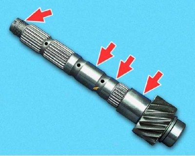
Transmission output shaft assembly: 1 - secondary shaft; 2 - synchronizer of 1st and 2nd gears; 3 – a gear wheel of the 3rd transfer; 4 – a gear wheel of the 4th transfer; 5 - rear shaft bearing; 6 - synchronizer of 3rd and 4th gears; 7 - gear wheel of the 2nd gear; 8 - gear wheel of the 1st gear; 9 - the inner ring of the front shaft bearing
You will need:
- key "at 32"
- bearing press mandrel
- two screwdrivers
- goatee
- hammer
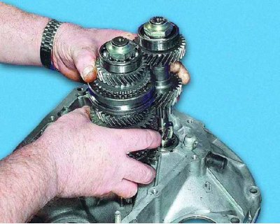
1. To disassemble the secondary shaft, it is necessary to unscrew the nut at its rear end, which is wrapped with a large moment. To do this, install the primary and secondary shafts in the clutch housing...
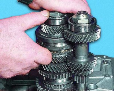
2....shift into 4th gear, then...
3....2nd gear...
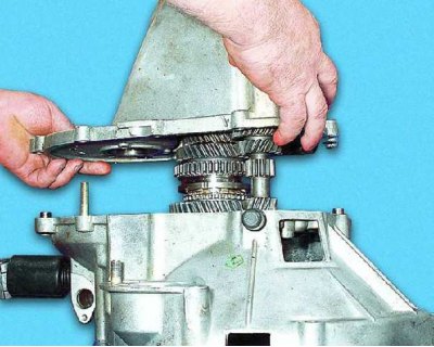
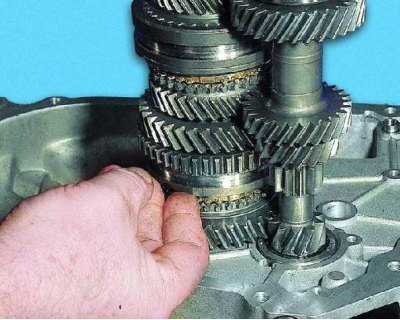
4.... install the gearbox housing and tighten the three housing mounting bolts evenly around the perimeter...
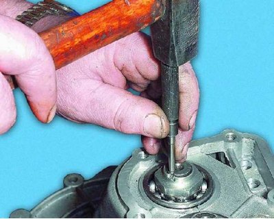
5.... unscrew the output shaft nut and...
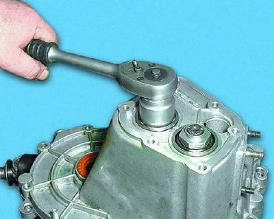
6.... while holding the gearbox from moving, unscrew the output shaft nut. Loosen the input shaft nut if necessary.
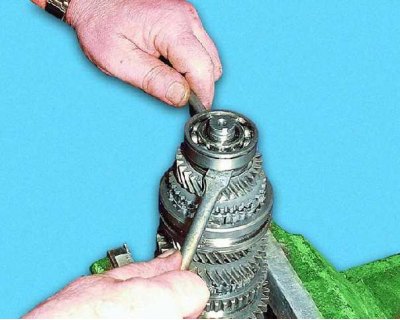
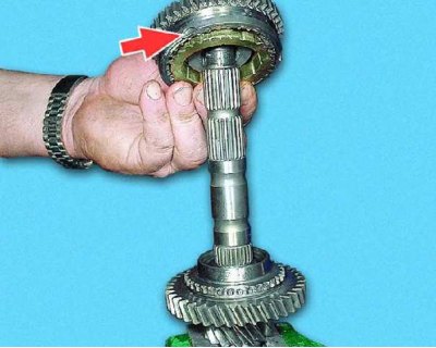
7. Clamp the output shaft in a vise with soft metal jaws and use two large screwdrivers to compress the rear bearing.
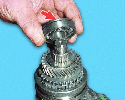
8. Remove the bearing from the shaft. At the same time, please note that it is installed on the shaft with a groove under the retaining ring to the end of the shaft.
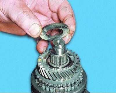
9. Remove the thrust washer.
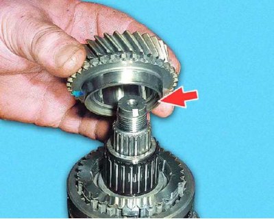
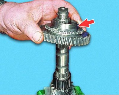
10. Remove the 4th gear. Note that the cone on the gear is pointing towards the synchronizer.
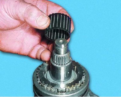
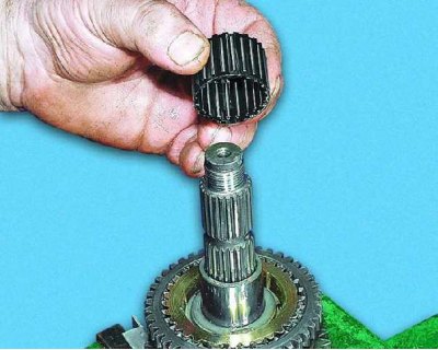
11. Remove the 4th gear needle bearing.
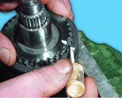
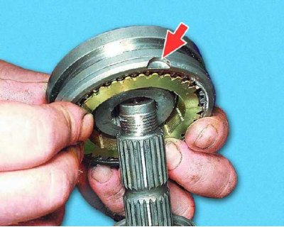
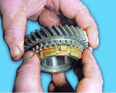
12. Mark the position of the blocking ring relative to the synchronizer sleeve. During operation, the teeth of the ring are run in to the teeth of the coupling, therefore, during assembly, the ring must be installed in the same position.
13. Remove the blocking ring of the 4th gear of the synchronizer.
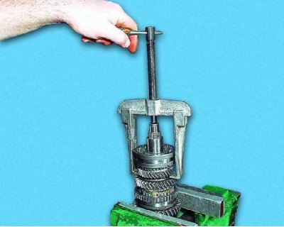
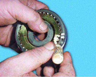
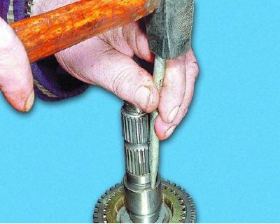
14. Using a puller, press the 3rd and 4th gear synchronizer and needle bearing bush off the shaft.
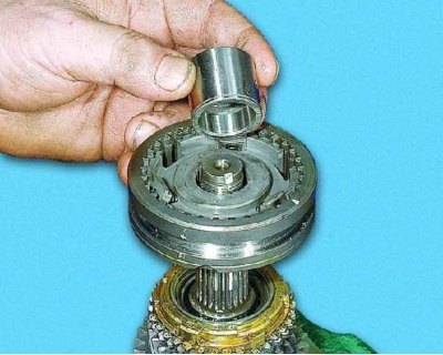
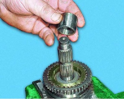
15. Remove the needle bearing bushing and...
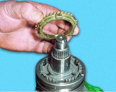
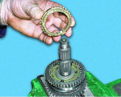
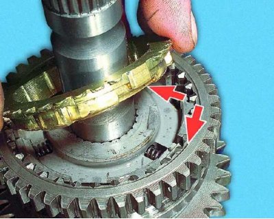
16.... synchronizer with 3rd gear blocking ring. Please note: the recesses on the synchronizer clutch are directed towards the 3rd gear.
17. Mark the position of the ring relative to the synchronizer sleeve.
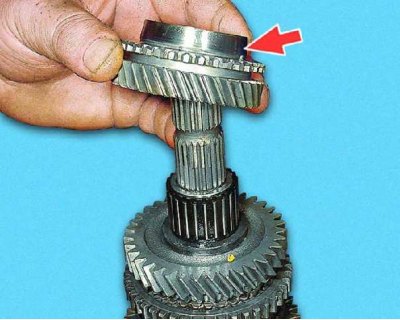
18. Remove the 3rd gear. Please note: the cone on the gear is directed towards the synchronizer.
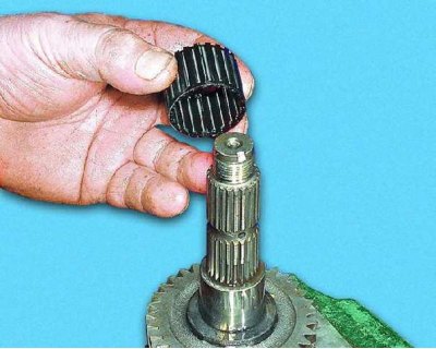
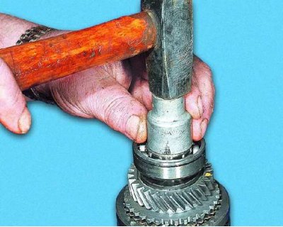
19. Remove the 3rd gear needle bearing.
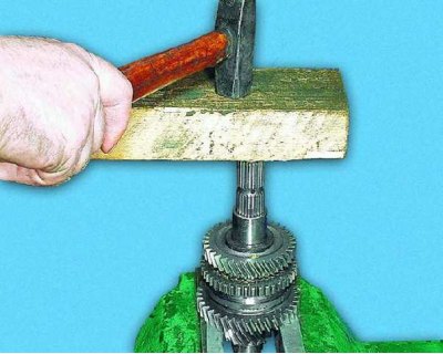
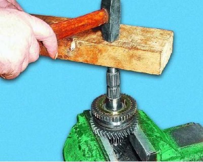
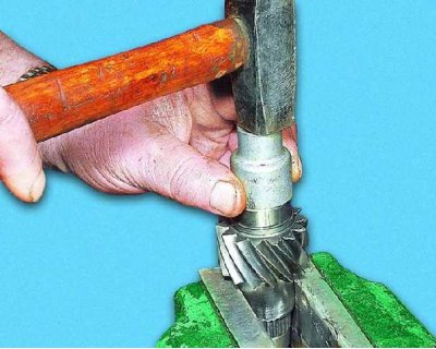
20. Using a hammer on the end of the shaft through a wooden gasket, press the 3rd gear needle bearing bushing off the shaft (first slightly open the vise jaws).
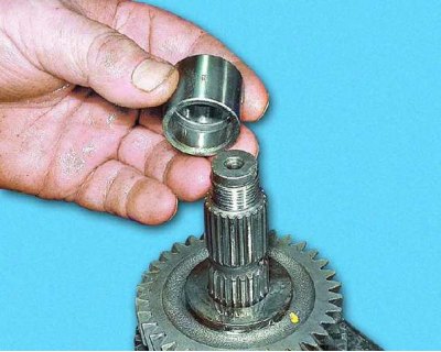
21. Remove the 3rd gear needle bearing bush...
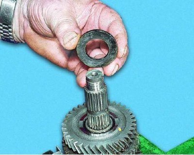
22....thrust washer and...
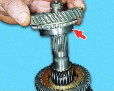
23.... the 2nd gear from the shaft. Note that the cone on the gear is pointing towards the synchronizer.
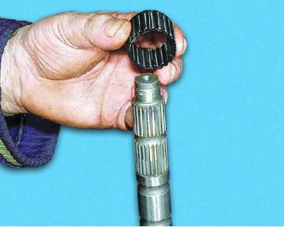
24. Remove the 2nd gear needle bearing.
25. Press the 1st and 2nd gear synchronizer and 2nd gear needle bearing bushing off the shaft with hammer blows through the wooden spacer.
26. Remove the 2nd gear needle bearing bush...
27.... 2nd synchro locking ring (having previously noted the position of the ring relative to the coupling) And...
28.... synchronizer with 1st gear blocking ring. Note that the notches on the synchro clutch point towards the 1st gear. Mark the position of the ring relative to the synchronizer sleeve.
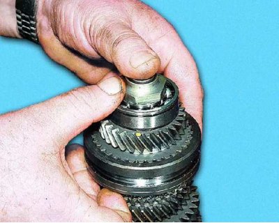
29. Remove the 1st gear from the shaft. Note that the cone on the gear is pointing towards the synchronizer.
30. Remove the 1st gear needle bearing.
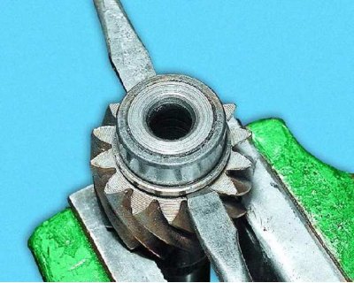
31. If necessary, turn the shaft over and compress the inner race of the front roller bearing of the secondary shaft.
32. Thoroughly clean, rinse and dry the output shaft parts.
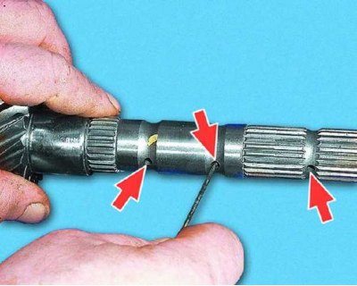
33. Check the condition of the shaft. If there are signs of wear on the bearing journals, the shaft must be replaced.
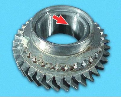
34. Check the condition of the gears. If there are chipping and chipping of the teeth, scuffing on the inner surfaces or signs of wear on the working surfaces of the teeth, replace the gears.
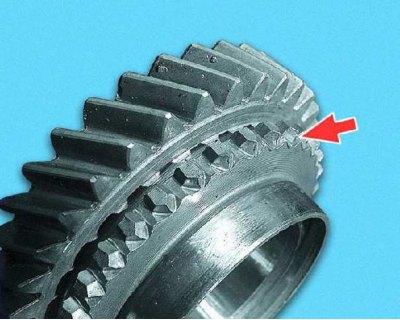
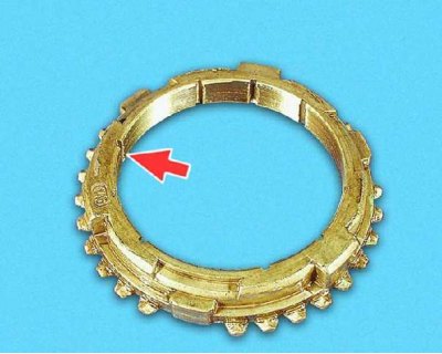
35. Replace gears that have significant crushing or chips on the ends of the teeth of the spline ring.
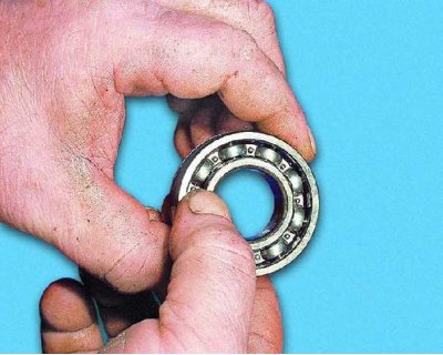
36. Check the ease of rotation of the bearing. If the raceways or balls are damaged, or if play is found in the bearing (the radial clearance in it should not exceed 0.04 mm) replace the bearing.
37. Check up a condition of blocking rings of synchronizers. If there are nicks and chips on the gear rims or significant wear on the cones, replace the blocking rings.
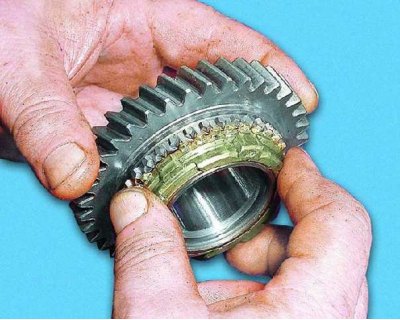
38. Check the clearance between the gears and the corresponding locking rings. For this "grind", firmly pressing and turning the blocking ring several times to the gear cone, and...
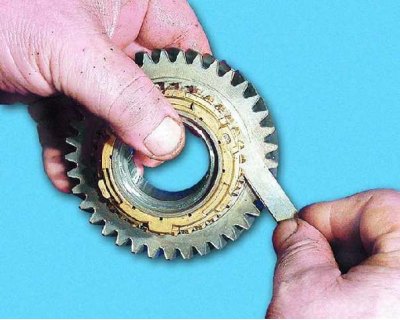
39....measure the clearance with a flat feeler gauge. The minimum allowable gap is 0.6 mm. If it is less, the blocking ring must be replaced.
40. After replacing the blocking ring, also check the gap between the new ring and the gear. Shake the ring - play is unacceptable.
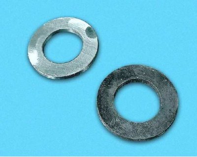
41. Check the condition of the thrust rings. If scuffing or deformation is found, replace the rings.
42. Before assembling the output shaft, clean the oil passages.
43. Using a suitable mandrel, press on the inner race of the front bearing until it stops.
44. Assemble the output shaft in the reverse order of removal. Press the details of the secondary shaft to the stop with the help of a beard, applying force evenly over the entire circumference.
45. Install the old blocking rings in accordance with the previously made marks. Install the new rings so that the small protrusions on the ring (there are no teeth opposite) coincided with the grooves of the synchronizer hub in the places where the clamps are installed.
46. Press on the shaft rear bearing using a suitable mandrel, applying force only to the inner race of the bearing.
47. After assembly, check the operation of the synchronizers. To do this, move the synchronizer clutches manually to the appropriate gear engagement position. Finally tighten and lock the rear shaft bearing nut (see steps 1-4).