




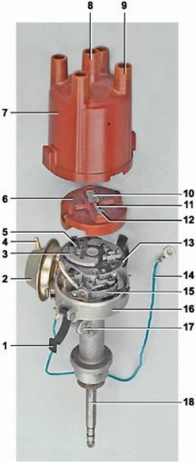
Distributor details: 1 - spring lid holder; 2 - vacuum ignition timing regulator; 3 - weight; 4 - vacuum supply nipple; 5 - spring; 6 - rotor (runner); 7 - distributor cap; 8 - central electrode with terminal for wire from ignition coil; 9 - side electrode with terminal for wire to spark plug; 10 - central contact of the rotor (runner); 11 - resistor; 12 - outer rotor contact; 13 - ignition timing regulator support plate; 14 - wire connecting the distributor to the output of the primary winding of the ignition coil; 15 - contact group of the breaker; 16 - distributor housing; 17 - capacitor; 18 - distributor shaft
On vehicles with contact ignition system, distributor model 30.3706 is installed.
The distributor consists of an aluminum housing, a shaft, a contact breaker, centrifugal and vacuum ignition advance regulators, a rotor (runner) and a plastic cover secured on top of the housing with two spring holders.
The ignition distributor is installed in the opening of the cylinder block of the left front part of the engine. The distributor shaft is driven by the auxiliary drive gear, into the splined opening of which the shaft shank is inserted. The shaft rotates in a porous metal-ceramic bushing pressed into the upper part of the distributor housing. Lubrication is supplied to the bushing from the oiler on the side of the housing.
A plastic rotor (runner) of the distributor is fixed to the upper part of the shaft. The runner has a central and outer contact, connected through a resistor designed to suppress radio interference. The runner is fixed in a certain position with two screws on the support plate of the centrifugal ignition advance regulator.
The central contact of the runner is supported by a spring-loaded carbon electrode of the distributor cap, the output of which is connected to the high-voltage output of the coil. When the runner rotates, high-voltage pulses are transmitted from the outer contact of the runner to the side electrodes of the ignition distributor cap and then along the high-voltage wires to the spark plugs.
The breaker consists of a contact group and a cam with four projections. The contact group is secured with two screws on a movable plate. To adjust the position of the contact group on the plate, one of the mounting holes in the group is made oblong. The plate rotates on a ball bearing installed in the distributor housing. The breaker cam is made as part of the shaft. The surface of the cam is lubricated with a special wick - a felt installed on the movable plate. One contact of the contact group is on a movable spring-loaded lever, the other contact of the group is stationary. When the shaft rotates, the cam, pressing with a projection on the plastic block of the lever of the movable contact, opens the circuit supplying voltage to the primary winding of the ignition coil.
In order to prevent sparking on the open contacts of the breaker caused by a change in the magnetic flux in the primary winding of the coil, a capacitor is connected in parallel to the breaker circuit, secured with a screw to the distributor housing.
The initial ignition timing setting is set with the engine idling and is adjusted manually by turning the distributor housing (see "Ignition timing - checking and adjustment"). When the body is turned clockwise, the advance decreases, counterclockwise - increases.
In other engine operating modes, the advance is regulated automatically - by centrifugal and vacuum regulators.
The centrifugal regulator changes the ignition timing depending on the engine speed. The regulator consists of a support plate and a leading plate. The support plate is soldered to a bushing mounted on the distributor shaft with the ability to rotate 15° relative to the shaft. From above (on the base plate) two weights are installed on riveted axles. The leading plate is pressed onto the upper end of the distributor shaft. The plates are connected to each other by two springs of different stiffness. The springs, turning the support plate counterclockwise, press the weights against the leading plate and do not allow the weights to diverge under the action of centrifugal forces at low engine speeds. When the engine speed reaches 1000 rpm, the centrifugal force acting on the weights first overcomes the resistance of one spring, and when the speed increases, the other. The weights, turning on the axles and resting their cam surface against the leading plate, turn the support plate together with the runner clockwise (in the direction of rotation of the roller), increasing the ignition timing.
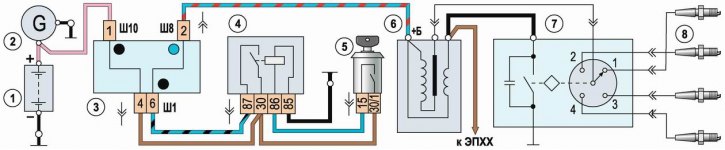
Contact ignition system diagram: 1 - battery; 2 - generator; 3 - relay and fuse box; 4 - ignition relay; 5 - ignition switch (lock); 6 - ignition coil; 7 - ignition distributor; 8 - spark plugs
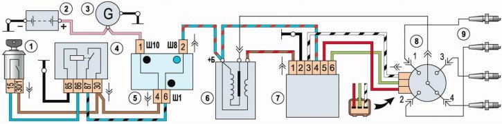
Contactless ignition system diagram: 1 - ignition switch (lock); 2 - battery; 3 - generator; 4 - ignition relay; 5 - relay and fuse box; 6 - ignition coil; 7 - Switch; 8 - ignition distributor; 9 - spark plugs
The vacuum regulator is secured with two screws to the distributor housing and changes the ignition timing depending on the engine load. The regulator diaphragm rod is connected by a rod to the movable breaker plate. The cavity behind the vacuum regulator diaphragm is connected by a hose to the cavity above the throttle valve of the primary carburetor chamber. When a vacuum is created in the regulator cavity, the diaphragm presses the return spring and the rod turns the movable breaker plate counterclockwise (against the direction of the roller movement), increasing the ignition timing.
The text is published on the portal VAZBOOK.RU
On cars with a contactless ignition system, the 3810.3706 distributor is installed. Structurally, it is made similar to the 30.3706 distributor, but instead of a contact group and a cam, it has a sensor and a screen with four cutouts, rigidly connected to the shaft. The sensor operates on the principle of induction. When the shaft rotates, the cutouts and projections of the screen pass through a groove in the sensor, causing a change in the magnetic field. Control pulses from the sensor are sent to the switch, which converts them into current pulses in the primary winding of the ignition coil.