
Brake system diagram
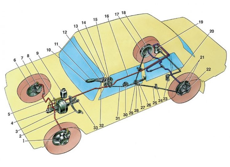
1 - brake disc; 2 - brake pedal; 3 - vacuum amplifier; 4 - the main cylinder of the hydraulic drive of the brakes; 5 – the pipeline of a contour of a drive of forward brakes; 6 – a protective casing of a forward brake; 7 - front brake caliper; 8 - vacuum pipeline; 9 – a tank of the main cylinder; 10 – button of the parking brake drive lever; 11 – parking brake drive lever; 12 – lever latch rod; 13 – lever latch; 14 – an arm of the lever of a drive of a parking brake; 15 - return lever; 16 – the pipeline of a contour of a drive of back brakes; 17 - flange of the tip of the cable sheath; 18 - rear brake wheel cylinder; 19 - rear brake pressure regulator; 20 - pressure regulator drive lever; 21 - brake pads; 22 – the lever of a manual drive of pads; 23 - thrust lever drive pressure regulator; 24 - bracket for fastening the tip of the cable sheath; 25 - rear cable; 26 - locknut; 27 - adjusting nut; 28 - bushing; 29 - rear cable guide; 30 - guide roller; 31 - front cable; 32 – an emphasis of the switch of a control lamp of a parking brake; 33 - brake light switch
The car is equipped with two independent brake systems: working and parking. The first provides braking when the car is moving and has a hydraulic drive, the second slows down the car in the parking lot, has a mechanical drive.
The service brake system has two circuits that provide independent drive of the front and rear wheel brakes. Both circuits are actuated from one pedal 2, which, using a bracket, is attached together with the clutch pedal to the front panel of the body.
In addition to the brake pedal, the hydraulic drive includes:
- master brake cylinder 4;
- vacuum booster 3;
- tank 9 of the master cylinder;
- rear brake pressure regulator 19;
- brake mechanisms of front and rear wheels together with working cylinders;
- pipelines.