
Service brake system It is designed to reduce the speed of the car, up to its complete stop and briefly hold the car in a stationary state.
The working brake system is double-circuit, diagonal, with a hydraulic drive, consists of a master brake cylinder with a vacuum booster, four wheel brakes and a fluid pressure regulator in the rear brakes. The brake mechanisms of the front wheels are disc, ventilated, the rear wheels are drum.
Note. Part of the cars VAZ 2110, VAZ 2111, VAZ 2112 of the early years of production with 8-valve engines of 1.5 liters. equipped with front wheel brakes with non-ventilated discs.
Each of the contours of the car includes the brake mechanisms of two wheels: one front and one rear located diagonally on the car.
So one circuit includes the brake mechanisms of the front right and rear left wheels, and the second circuit includes the brake mechanisms of the front left and rear right wheels. If one of the circuits fails, the second circuit, albeit with less efficiency, will ensure the car stops.
The pressure regulator limits the flow of brake fluid to the rear brake mechanisms when there is insufficient load on the rear axle, thereby preventing the rear wheels from locking and skidding the rear axle of the car during heavy braking. In the case of the brake force regulator there is a control hole closed with a plastic plug. Leakage of brake fluid from this hole indicates leaks in the brake force regulator rings.
To reduce the effort applied by the driver to the brake pedal, a vacuum booster is installed on the main brake cylinder, which works by using the vacuum formed in the inlet pipeline of a running engine.
Warning. Do not turn off the engine until the vehicle has come to a complete stop.
A reservoir with brake fluid is installed on the body of the master brake cylinder. A sensor is installed in the reservoir cap of the master brake cylinder. In case of a dangerous drop in the level of brake fluid in the tank, the sensor turns on a warning lamp on the instrument panel.
Hand brake system designed to prevent spontaneous movement of the car during parking.
The hand brake lever is connected by two cables to the brake mechanisms of the rear wheels. When the handbrake lever is moved to the upper position, the levers mounted on the pads turn and begin to put pressure on the spacer bars. The brake pads of the rear brake mechanisms move apart and fix the brake drum from turning.
During operation, the handbrake requires periodic adjustment. This is due to the wear of the brake pads and the pulling of the drive cables. The handbrake lever travel should be 2-4 clicks. If it is less, it is necessary to increase the length of the drive; if it is more, reduce it.
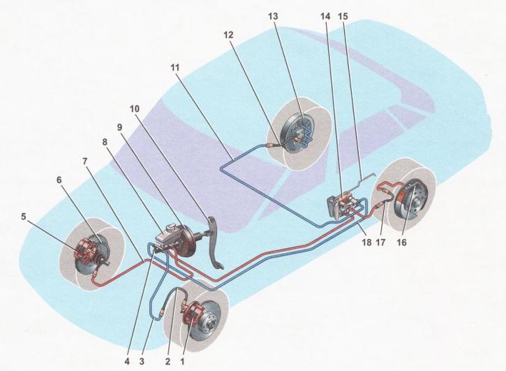
Scheme of the brake system: 1 - brake mechanism of the front left wheel; 2, 6, 12, 17 - brake hoses; 3, 7, 11, 18 - brake pipes; 4 - main brake cylinder; 5 - brake mechanism of the front right wheel; 8 - reservoir of the main brake cylinder; 9 - vacuum amplifier; 10 - brake pedal; 13 - brake mechanism of the rear right wheel; 14 - brake fluid pressure regulator in the brake mechanisms of the rear wheels; 15 - brake fluid pressure regulator lever in the rear wheel brakes; 16 - rear left wheel brake
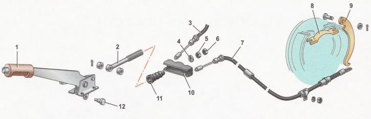
Diagram of the hand brake device: 1 - hand brake drive lever; 2 - lever rod; 3 - cable for the brake mechanism of the right rear wheel; 4 - washer; 5 - adjusting nut; 6 - locknut; 7 - cable for the brake mechanism of the left rear wheel; 8 - spacer bar; 9 - lever; 10 - cable equalizer; 11 - rubber cover; 12 - thrust axis