
Cross section of pendulum arm bracket
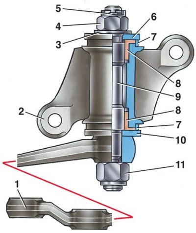
1 - pendulum lever; 2 – bracket body; 3 - washer; 4 - adjusting nut; 5 - cotter pin; 6 - top washer; 7 - sealant; 8 - bushing; 9 - the axis of the lever; 10 - bottom washer; 11 - self-locking nut
Removal and disassembly
1. To remove the pendulum arm bracket, separate the pendulum arm from the ball pins of the middle and side right rods by unpinning and unscrewing the nuts first and removing the ball pins from the lever sockets with a puller A.47035. Then turn away bolts of fastening of an arm to a side member and remove an arm.
2. Fix the bracket in a vice, unpin and unscrew nut 4, then remove washers 3 and 6 and pendulum lever 1 complete with axle 9, washer 10 and self-locking nut 11, remove seals 7 and press out bushings 8.
Examination
1. Check the condition of the pendulum arm axle bushings; if you find an ovality or an unacceptable gap between them and the axle, then replace the bushings with new ones.
2. Check the axle for ovality and damage, replace it with a new one if necessary. Make sure the pendulum arm is not deformed; otherwise, replace it with a new one.
Assembly and installation
1. Before assembly, lubricate the pendulum arm axle bushings and fill the space between them with LITOL-24 grease. The assembly procedure for the pendulum arm bracket is the reverse of disassembly.
2. If the axle 9 has been replaced, then tighten the self-locking nut 11 of the lever fastening with a torque wrench.
3. Washer 6 is installed with bulges up.
4. After tightening the nut 4, the lever in the horizontal position must not rotate under its own weight. It should rotate under the action of a force of 9.8-19.6 N (1–2 kgf), attached at its end.
5. If nut 4 is overtightened, unscrew it, lift washer 6 and tighten again.
6. After securing the bracket to the side member with two bolts with self-locking nuts and flat washers, tighten the nuts with a torque wrench.
7. Connect the ball pins of the rods to the pendulum lever.