
Steering
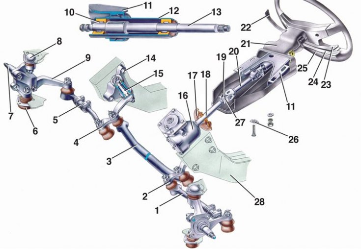
1 - lateral thrust; 2 - bipod; 3 - medium thrust; 4 - pendulum lever; 5 - adjusting clutch; 6 - lower ball joint of the front suspension; 7 - right rotary fist; 8 - upper ball joint of the front suspension; 9 – the right lever of a rotary fist; 10 – the bearing of the top shaft of a steering; 11 – an arm of fastening of a shaft of a steering; 12 – a pipe of an arm of fastening of a shaft of a steering; 13 – the top shaft of a steering; 14 – pendulum arm bracket; 15 - the axis of the pendulum lever; 16 - steering gear housing; 17 - shaft seal; 18 - worm shaft; 19 - universal joint; 20 – an intermediate steering shaft; 21 - facing casing; 22 - switch lever for windshield wipers and washer and headlights; 23 – the lever of the switch of light of headlights; 24 – the lever of the switch of indexes of turn; 25 - steering wheel; 26 - fixing plate of the front of the bracket; 27 – a coupling bolt of fastening of the universal joint; 28 - body spar
Section of the crankcase of the steering mechanism
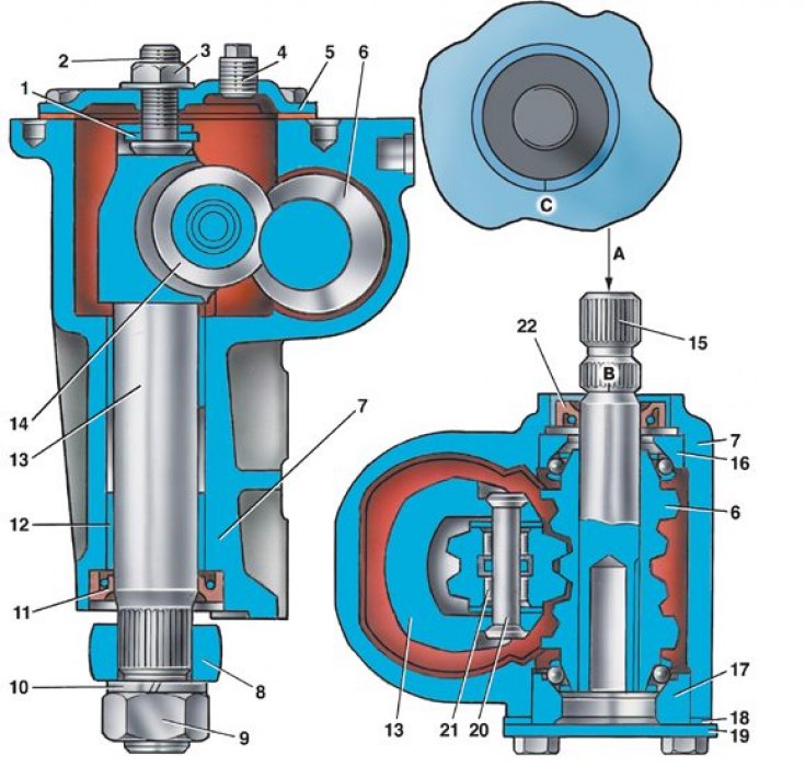
1 - plate of the adjusting screw of the bipod shaft; 2 - adjusting screw of the bipod shaft; 3 - adjusting screw nut; 4 - oil filler plug; 5 - cover of the crankcase of the mechanism; 6 - worm; 7 - crankcase of the steering mechanism; 8 - bipod; 9 - nut for fastening the bipod to the shaft; 10 - spring washer of the bipod fastening nut; 11 - bipod shaft seal; 12 - bronze bushing of the bipod shaft; 13 - bipod shaft; 14 - bipod shaft roller; 15 - worm shaft; 16 - upper ball bearing; 17 - lower ball bearing; 18 - adjusting shims; 19 - the lower cover of the worm bearing; 20 - roller axis; 21 - needle bearing; 22 - worm shaft seal; B, C - labels A - coincidence of labels
The car is equipped with a steering with a worm gear and a safety steering column. Steering shaft composite, consists of top 13 (see pic. Steering) and intermediate 20 shafts. The shaft 18 of the worm and the upper shaft 13 are interconnected by an intermediate shaft 20 with cardan joints at the ends. Joints on needle bearings, one-piece.
The upper shaft is mounted in the tube of the bracket 11 on two needle bearings with rubber bushings. The bearings in the pipe are rolled. Bracket 11 is attached to the body panel bracket at four points: from below with bolts with fixing plates 26, from above - on welded bolts with nuts and washers.
In a head-on collision, the edges of the fixing plates are deformed and slip through the holes of the bracket 11. Due to the folding of the steering shaft, the steering wheel leaves the driver's chest area, which reduces the likelihood and severity of injury.
The worm shaft, for this type of steering, is long. At the bottom of the worm shaft, as well as at the end of the crankcase 7 (see fig. Section of the crankcase of the steering mechanism) of the steering mechanism, marks are made in the form of marks B and C, if they coincide, the bipod shaft roller is installed in the middle of the worm. In this case, the steering wheel hub must be horizontal.
The steering gear housing is attached to the left side member 28 (see pic. Steering) body on the inside of the engine compartment with three bolts.
In crankcase 7 (see fig. Section of the crankcase of the steering mechanism) a worm 6 is located, which is engaged with a double-ridged roller 14 of the bipod shaft 13. The gear ratio of the worm pair is 16.4. The worm rotates in the upper 16 and lower 17 bearings, the balls of which are located on the treadmills of the ends of the worm. The axial clearance in the worm bearings is regulated by the selection of gaskets 18 between the crankcase and the cover 19. The bipod shaft rotates in two bushings 12 pressed into the steering gear housing. At the upper end of the shaft, roller 14 rotates on a needle bearing, and a bipod 8 is put on the lower end of the shaft, which has conical splines, and a bipod 8 is put on and fastened with a nut 9. Two double cavities are made in the spline hole of the bipod, and two double protrusions are made on the shaft. Therefore, the bipod can be mounted on the shaft in only one position.
The engagement of the roller with the worm is adjusted by screw 2. The axial clearance between the screw head and the shaft groove is eliminated by selecting adjusting plates 1.
The steering gear includes three rods - middle 3 (see pic. Steering) and two extreme 1, as well as a bipod 2, a pendulum arm 4 with a bracket 14 and swivel arms 9 of the knuckles 7. The middle rod is one-piece, has ball joints at the ends for connection with the pendulum arm and steering arm. Each side rod consists of two threaded ends connected to each other by an adjusting sleeve 5. The sleeves are fixed on the rods with the help of tie-down collars. The rotation of the clutch 5 changes the length of the lateral thrust when adjusting the toe of the front wheels. The ends of the extreme rods with the help of hinges are attached to the levers 9 of the steering knuckles, to the pendulum lever 4 and to the steering arm 2.
The ball joint of the rods consists of a steel pin 1 (see fig. Cross section of the ball joint), the spherical head of which is covered by a conical split plastic insert 4, which is pressed by the spring 5 to the body 3, due to which an interference is created in the connection of the pin with the insert and the thrust tip.
Bracket 14 (see pic. Steering) the pendulum lever is attached with two bolts to the right side member of the body opposite the steering gear housing. In bracket 2 (see fig. Cross section of pendulum arm bracket) two plastic bushings 8 are installed, in which the axis 9 rotates. The mechanical seal of the bushings is provided by seals 7 and washers 6 and 10.