
English Русский
Български
Беларускі
Український
Српски
Hrvatski
Română
Polski
Slovenský
Magyar
| Articles | Contacts | Sitemap |   
Repair and maintenance Lada Repair and maintenance Mazda Repair and maintenance Mitsubishi Repair and maintenance Toyota Repair and maintenance Land Rover Repair and maintenance Hyundai Repair and maintenance Nissan
VAZbook.ru


Main     1111   2101   2105   2106   2107   2109   2110   2115   2121  
VAZ-2104 (1984-2012) VAZ-2105 (1979-2010) VAZ-21051 (1979-2010)
  • Main
  • «Zhiguli»
  • VAZ-21051
  • Chassis
  • Steering
  • Disassembly and assembly of the steering gear housing

Disassembly and assembly of the steering gear housing (VAZ-21051)

            0

Contents: Disassembly ↓ Assembly ↓

Steering gear housing parts
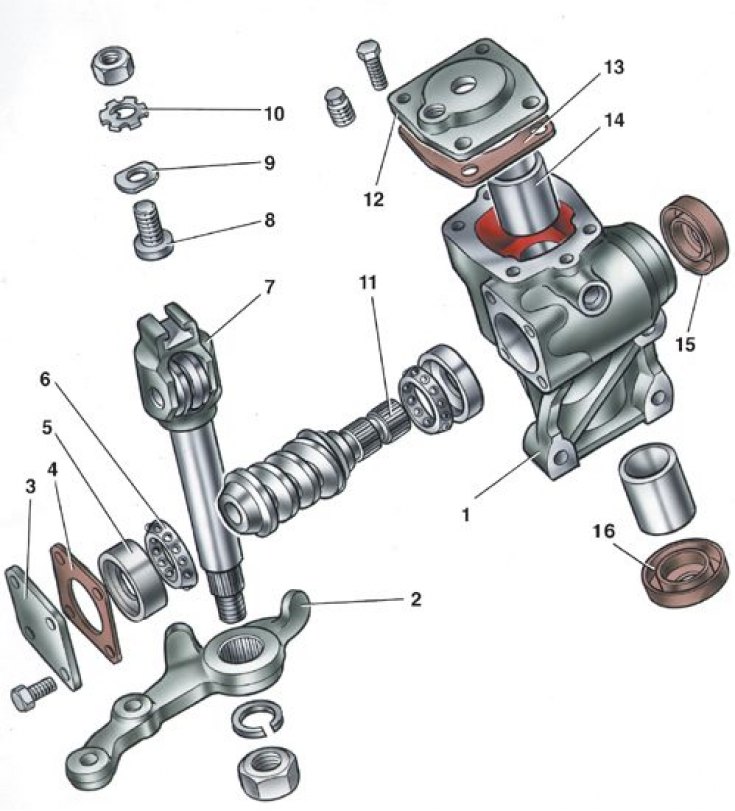


1 – crankcase; 2 – bipod; 3 – lower crankcase cover; 4 – adjusting shims; 5 – outer ring of worm…

1 – crankcase; 2 – bipod; 3 – lower crankcase cover; 4 – adjusting shims; 5 – outer ring of worm shaft bearing; 6 – ball separator; 7 – bipod shaft; 8 – adjusting screw; 9 – adjustment plate; 10 – lock washer; 11 – worm shaft; 12 – Upper crankcase cover; 13 – sealing gasket; 14 – knuckle shaft sleeve; 15 – worm shaft seal; 16 – knuckle shaft seal


Removal the bipod
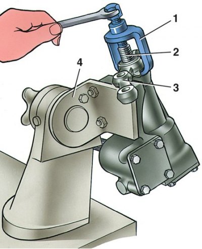


1 – puller A.47043; 2 – steering knuckle shaft; 3 – bipod; 4 – bracket A.74076/R

1 – puller A.47043; 2 – steering knuckle shaft; 3 – bipod; 4 – bracket A.74076/R


Control of the friction torque of the worm with a dynamometer
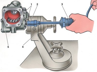


1 - worm; 2 – head A.95697/5; 3 – dynamometer 02.7812.9501; 4 – bracket for repair stand of…

1 - worm; 2 – head A.95697/5; 3 – dynamometer 02.7812.9501; 4 – bracket for repair stand of steering gear housing; 5 – steering gear housing


Disassembly


1. Drain the oil from the steering gear housing. Fasten the housing to the bracket A.74076/R with the support A.74076/1.

The source is on the website (VazBook.ru)

2. Having unscrewed the nut securing the steering knuckle 2 (see fig. Steering gear housing parts) and removing the spring washer, using tool 1 (puller A.74043) remove the bipod (see fig. Removing the bipod). After unscrewing the mounting bolts, remove cover 12 (see fig. Steering gear housing parts) steering gear housing together with adjusting screw 8, adjusting plate 9, lock washer 10 and lock nut. Remove shaft 7 of the steering arm from housing 1 together with the roller.

3. After unscrewing the mounting bolts, remove cover 3 of the worm shaft thrust bearing together with adjusting linings 4.

4. Using worm shaft 11, push outer bearing ring 5 out of the crankcase and remove the shaft together with bearing separators 6. Remove worm shaft seal 15 and pitman shaft seal 16.
4. Using worm shaft 11, push outer bearing ring 5 out of the crankcase and remove the shaft…


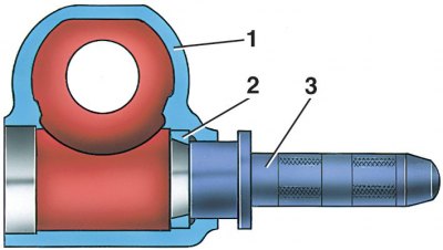
5. Device 3 (mandrel 67.78853.99541) press out the outer ring 2 of the upper bearing (1 – steering gear housing).

Assembly


1. Assemble the steering mechanism on bracket A.74076/R in the reverse order of disassembly.


2. Press the outer ring of the upper worm bearing with the 67.7853.9541 mandrel, moving the nozzle on the mandrel handle to the opposite side.
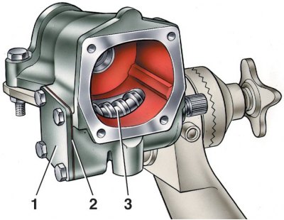
2. Press the outer ring of the upper worm bearing with the 67.7853.9541 mandrel, moving the nozzle…


3. After installing worm 3 in the steering gear housing and securing lower cover 1, check using dynamometer 02.7812.9501 and head A.95697/5 (see fig. Control of the friction torque of the worm with a dynamometer) friction moment of the worm shaft; it should be within the range of 19.6–49 N cm (2–5 kgf cm). If the torque is less than specified, reduce the thickness of the adjusting shims 2, and if more, increase it.

4. After installing the bipod shaft, check for any gap and engagement of the roller with the worm in the positions of the worm shaft turned to the right and left by 300 from the neutral position of the bipod. Eliminate any possible gap in engagement with adjusting screw 2 (see Fig. Section of the steering gear housing) and tighten lock nut 3.

5. After adjusting the clearance in the engagement of the roller and worm, check the friction torque of the worm shaft with a dynamometer, which should be equal to 68.6–88.2 N cm (7–9 kgf cm) when turning the worm shaft 300 both to the left and to the right from the middle position and should decrease smoothly to 49 N cm (5 kgf cm) when turning from an angle of 300 to the stop.

6. After completing the assembly, check the angles of rotation of the pitman arm from the neutral position, which should be 32°10'±1° both to the left and to the right until the pitman arm stops at the bolt heads, pour 0.215 l of TAD-17i transmission oil into the steering gear housing.


This article is available at russian, bulgarian, belarusian, ukrainian, serbian, croatian, romanian, polish, slovak, hungarian
The text was reviewed by the specialist: Grigory Vologodtsev

Share with friends:

Previous articles
VAZ-21051: Steering
Next articles

Removal and installation the steering gear
Adjusting the clearance in the engagement of the roller with the steering gear worm
Adjusting the clearance in the steering worm bearings
Checking the ball joints of the steering rods
General inspection of the steering system
Checking and repairing the steering mechanism
Upper Steering Shaft — Disassembly and Assembly
Steering linkages and ball joints
Pendulum arm bracket

More articles from other manuals on VAZ cars:
➠ Disassembly and assembly of the steering gear housing VAZ-21011 (1974-1983)
➠ Disassembly and assembly of the steering gear housing VAZ-2121 (1977-1994)
➠ Steering gear assembly VAZ-1111 (1988-1996)
➠ Steering gear engagement — adjustment VAZ-2106 (1976-2006)
➠ Steering gear engagement — adjustment VAZ-2107 (1982-2012)
Link in different formats to this page


Visitor comments

No comments yet


How much will 23 + 21 ?


VAZ-2104 (1984-2012) 
  • General information
  • Operation and maintenance
  • Power unit
  • Engine repair
  • Fuel system (carburetor)
  • Fuel system (injector)
  • Control system
  • Cooling system
  • Exhaust system
  • Transmission
  • Clutch
  • Car gearbox
  • Cardan gear
  • Rear axle
  • Chassis
  • Front suspension
  • Rear suspension
  • Wheels and tires
  • Steering
  • Brake system
  • Body
  • Exterior
  • Interior
  • Doors and glass
  • Ventilation and heating
  • Electrical equipment
  • Equipment and devices
  • Headlights and lighting
  • Engine electrics
  • Electrical circuits


VAZ-2105 (1979-2010) 
  • General information
  • Vehicle description
  • Vehicle device
  • Vehicle operation
  • Maintenance
  • Power unit
  • Engine repair
  • Cooling and lubrication system
  • Supply system
  • Transmission
  • Clutch
  • Car gearbox
  • Cardan gear
  • Rear axle
  • Chassis
  • Suspension and shock absorbers
  • Steering
  • Brake system
  • Body
  • Body elements
  • Electrical equipment
  • Engine electrics
  • Equipment and devices


VAZ-21051 (1979-2010) 
  • General information
  • Introduction to guide
  • User manual
  • Troubleshooting
  • Power unit
  • Engine repair
  • Engine repair VAZ-2103
  • Cooling system
  • Lubrication system
  • Power and exhaust system
  • Fuel injection
  • Transmission
  • Clutch
  • Car gearbox
  • Cardan gear
  • Rear axle
  • Chassis
  • Suspension and shock absorbers
  • Steering
  • Brake system
  • Body
  • Exterior
  • Interior
  • Doors and windows
  • Electrical equipment
  • Equipment and devices
  • Engine electrics
  • Ignition system
  • Electrical circuits


VAZbook.ru © 2017 · Mobile version · Contact with administration · Sitemap: EN BG BY UA RS HR RO PL SK HU · Site search · News and articles VAZ-1111 · VAZ-11113 · VAZ-2101 · VAZ-21011 · VAZ-2104 · VAZ-2105 · VAZ-21051 · VAZ-2106 · VAZ-21061 · VAZ-2107 · VAZ-21099 · VAZ-2109 · VAZ-2108 · VAZ-2110 · VAZ-2112 · VAZ-2114 · VAZ-2115 · VAZ-2121 · VAZ-21213 · VAZ-21214 ·
The site stores technical data using cookies to improve the service.