
English Русский
Български
Беларускі
Український
Српски
Hrvatski
Română
Polski
Slovenský
Magyar
| Articles | Contacts | Sitemap |   
Repair and maintenance Lada Repair and maintenance Mazda Repair and maintenance Mitsubishi Repair and maintenance Toyota Repair and maintenance Land Rover Repair and maintenance Hyundai Repair and maintenance Nissan
VAZbook.ru


Main     1111   2101   2105   2106   2107   2109   2110   2115   2121  
VAZ-2108 (1984-2003) VAZ-2109 (1984-1997) VAZ-21099 (1990-2004)
  • Main
  • «Sputnik»
  • VAZ-2108
  • Chassis
  • Front suspension
  • Removal and installation the front suspension

Removal and installation the front suspension (VAZ-2108)

            0

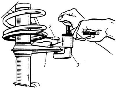
To remove the suspension, place the vehicle on a lift or inspection pit and apply the parking brake. Remove the hub cap, loosen the front wheel mounting bolts and unscrew the hub mounting nut. Raise the front of the vehicle and remove the front wheel. Use puller A.47035 (3 — figure 86) press out the ball joint pin 2 of the steering rod from the steering arm 1 of the suspension strut. Disconnect the strut 5 (see figure 85) of the anti-roll bar from the arm 1 of the suspension and the bracket 10 of the tie rod from the body. Disconnect the ball joint of the suspension arm from the steering knuckle. In this case, when unscrewing the bolts fastening the ball joint to the steering knuckle, use only a socket wrench so as not to damage the boot 14 of the joint.

Figure 86. Pressing out the ball joint pin of the steering rod from the steering column pivot arm

Figure 86. Pressing out the ball joint pin of the steering rod from the steering column pivot arm


Disconnect the suspension arm 1 from the body bracket 4 and remove the arm assembly with the tensioner 8 and bracket 10. Unscrew the bolts 11 securing the shoe guide to the steering knuckle 12, hang the caliper assembly with the shoes on a technological hook to the body so that the hose is not loaded.


By moving the stand 6 to the side and turning it, the splined tail of the constant velocity joint is removed from the wheel hub. From the engine compartment side, the protective cap of the support is removed, nuts 1 (see figure 82) fastening the telescopic strut to the body and remove the front suspension strut assembly with the steering knuckle and wheel hub.

While performing the above operations, remove the other front suspension strut. Then remove struts 5 (see figure 85), unscrew the nuts securing the anti-roll bar to the body and carefully remove the anti-roll bar from under the exhaust pipe.

Installation of front suspension components and parts is carried out in the reverse order of removal, taking into account the following:
  • the front strut nuts, the nuts of the suspension arm mounting bolts to the body brackets, the nuts of the stabilizer struts mounting to the suspension arms and the nuts of the stabilizer bar mounting to the body are pre-tightened until the clearances in the joints are selected;
  • all nuts securing rubber-metal hinges, rubber bushings and cushions are finally tightened to the torques specified in Appendix 1, under a static load of 320 kg, which corresponds to the mass of 4 people and 40 kg of cargo in the trunk;
  • when installing bracket 10 (see figure 85) when fastening the strut to the body, care is taken not to damage the threads in the welded bushings of the body;
  • when installing the anti-roll bar, do not allow longitudinal displacement of the pads on the bar, as they must be located at the same distance from the center of the bar (the distance between the centers of the pillow brackets should be 700 mm). First, tighten the front mounting bolts of the 3 stabilizer cushion brackets (from the side of the cut of the pillows), and then the rear ones. At the same time, make sure that when tightening the bolts, the gap in the cushion cuts is completely eliminated and the cushions are not damaged.

On cars manufactured in 1985, UG-9 anaerobic glue was used in the splined connection of the wheel hub with the outer joint housing. In case of reuse of the wheel hub and joint housing, the glue is removed and immediately before assembly, the splines of the hub and joint are degreased and UG-9 anaerobic glue is applied to the splined part of the joint housing farthest from the threaded end in a 10-20 mm annular strip. After this, the wheel hub is put on and the hub fastening nut is tightened to a torque of 23-25 kgf·m. During the first 4 hours required for the polymerization of the glue, the car is transported by towing or under its own power, provided that it starts off smoothly, without jerks, at a speed of no more than 10 km/h.


This article is available at russian, bulgarian, belarusian, ukrainian, serbian, croatian, romanian, polish, slovak, hungarian
The text was reviewed by the specialist: Grigory Vologodtsev

Share with friends:

Previous articles
VAZ-2108: Front suspension
Next articles

Checking and adjusting wheel alignment angles
Checking the condition of the suspension parts on the car
Possible faults of the front suspension
Features of the front suspension device
Testing the telescopic strut and shock absorber on the stand
Disassembly and assembly of a telescopic stand
Disassembly and assembly of the tie rod suspension arm and its bracket
Disassembling and assembling the upper support of the suspension strut
Disassembly and assembly of the stabilizer

More articles from other manuals on VAZ cars:
➠ Front suspension device VAZ-1111 (1988-1996)
➠ Front suspension VAZ-2101 (1970-1983)
➠ Front suspension, front wheel hub of VAZ-2104 and VAZ-2105 cars VAZ-2105 (1979-2010)
➠ Front suspension device VAZ-2106 and VAZ-2103 VAZ-2106 (1976-2006)
➠ Description of the front suspension design VAZ-2107 (1982-2012)
Link in different formats to this page


Visitor comments

No comments yet


How much will 31 + 30 ?


VAZ-21099 (1990-2004) 
  • General information
  • Specifications
  • User manual
  • Maintenance
  • Car care
  • Troubleshooting
  • Power unit
  • Engine repair
  • Cooling and lubrication system
  • Power and exhaust system
  • Transmission
  • Car gearbox
  • Clutch and drive shafts
  • Chassis
  • Car suspension
  • Steering
  • Brake system
  • Body
  • Exterior
  • Interior
  • Doors and locks
  • Electrical equipment
  • Equipment and devices
  • Lighting and signaling
  • Engine electrics
  • Ignition system


VAZ-2109 (1984-1997) 
  • General information
  • Vehicle operation
  • Vehicle device
  • Power unit
  • Engine repair
  • Cooling and lubrication system
  • Supply system
  • Transmission
  • Clutch
  • Gearbox and drive
  • Chassis
  • Car suspension
  • Steering
  • Brake system
  • Body
  • Body elements
  • Electrical equipment
  • Engine electrics
  • Equipment and devices


VAZ-2108 (1984-2003) 
  • General information
  • Introduction to guide
  • Power unit
  • Engine repair
  • Cooling and lubrication system
  • Power and exhaust system
  • Transmission
  • Clutch and drive shafts
  • Car gearbox
  • Chassis
  • Front suspension
  • Rear suspension
  • Steering
  • Brake system
  • Body
  • Exterior
  • Interior
  • Doors and glass
  • Electrical equipment
  • Equipment and devices
  • Engine electrics
  • Ignition system


VAZbook.ru © 2017 · Mobile version · Contact with administration · Sitemap: EN BG BY UA RS HR RO PL SK HU · Site search · News and articles VAZ-1111 · VAZ-11113 · VAZ-2101 · VAZ-21011 · VAZ-2104 · VAZ-2105 · VAZ-21051 · VAZ-2106 · VAZ-21061 · VAZ-2107 · VAZ-21099 · VAZ-2109 · VAZ-2108 · VAZ-2110 · VAZ-2112 · VAZ-2114 · VAZ-2115 · VAZ-2121 · VAZ-21213 · VAZ-21214 ·
The site stores technical data using cookies to improve the service.