




Shock absorbers for front and rear suspensions
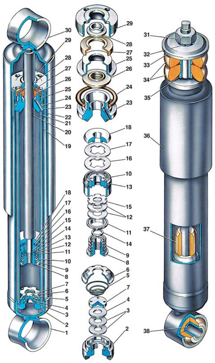
1 - lower eye; 2 – compression valve body; 3 – compression valve discs; 4 – compression valve throttle disc; 5 – compression valve spring; 6 – compression valve holder; 7 – compression valve plate; 8 – recoil valve nut; 9 – recoil valve spring; 10 – shock absorber piston; 11 – recoil valve plate; 12 – recoil valve discs; 13 – piston ring; 14 – recoil valve nut washer; 15 – throttle disc of the return valve; 16 – bypass valve plate; 17 – bypass valve spring; 18 – limiting plate; 19 – reservoir; 20 – rod; 21 – cylinder; 22 – casing; 23 – rod guide bushing; 24 – reservoir sealing ring; 25 – rod seal ring; 26 – rod seal; 27 – rod protective ring gasket; 28 – rod protective ring; 29 – reservoir nut; 30 – upper shock absorber eye; 31 – nut for fastening the upper end of the front suspension shock absorber; 32 – spring washer; 33 – shock absorber mounting cushion washer; 34 – pillows; 35 – spacer sleeve; 36 – Front suspension shock absorber casing; 37 – rod buffer; 38 – rubber-metal hinge
The shock absorbers of the front and rear suspensions differ in size, the method of fastening the upper part and the presence of a rebound buffer 37 at the front shock absorber, which limits the shock absorber travel during the rebound stroke. In addition, the front shock absorber has other operating characteristics.
The rear shock absorber consists of a reservoir 19 with an eye, a compression valve (pos. 2, 3, 4, 5, 6, 7), working cylinder 21, rod 20 with piston 10 and return and bypass valves and casing 22 with eye.
The reservoir 19 is made of a steel pipe, to the lower end of which the eye 1 is welded, and in the upper part a thread is cut for the nut 29. The housing 2 of the compression valve is inserted into the groove of the eye in assembly with the valve disks. It is pressed against the groove by the working cylinder 21. The annular space between the reservoir and the cylinder is filled with liquid. Inside the working cylinder there is a rod 20 with a piston 10. The piston has vertical channels located along two circles. The channels on the small circle are closed from below by disks 12 and 15 of the recoil valve, and on the larger one - from above by a plate 16 of the bypass valve.
[The original is available on the online resource: www.vazbook.ru]
The compression valve is located at the bottom of the cylinder. In the valve body 2 there is a seat, to which the spring 5 presses through the plate 7 the disks 3 and 4. The disk 4 is a throttle, has a cutout through which the liquid is throttled at a low piston speed. In the lower part of the valve body there is a cylindrical groove and four vertical channels, and in the holder 7 there are six side and one central holes, through which the liquid passes from the reservoir to the cylinder and back.
A guide bushing 23 is installed in the top of the cylinder, which is sealed in the reservoir by a ring 24, and the rod outlet is sealed by a gland 26 with a collar 25. All parts located in the upper part of the cylinder are pressed by a nut 29. Rubber-metal hinges 38 are pressed into the shock absorber lugs.