

Rear suspension
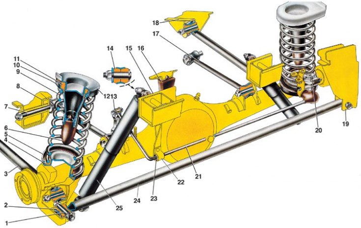
1 - spacer sleeve; 2 - rubber bushing; 3 - lower longitudinal rod; 4 - the lower insulating gasket of the spring; 5 - the lower support cup of the spring; 6 – compression stroke buffer; 7 – a bolt of fastening of the top longitudinal bar; 8 - bracket for fastening the upper longitudinal rod; 9 - suspension spring; 10 - the upper cup of the spring; 11 - the upper insulating gasket of the spring; 12 - spring support cup; 13 – draft of the lever of a drive of a regulator of pressure of back brakes; 14 - rubber bushing of the shock absorber eye; 15 - shock absorber mounting bracket; 16 - additional compression stroke buffer; 17 - upper longitudinal rod; 18 - bracket for fastening the lower longitudinal rod; 19 – an arm of fastening of a cross bar to a body; 20 - rear brake pressure regulator; 21 - pressure regulator drive lever; 22 – a clip of the basic plug of the lever; 23 - lever bushing; 24 - transverse rod; 25 - shock absorber
The rear suspension of the car is dependent, includes a guide device, elastic elements and devices that dampen body vibrations.
Guiding device. The rear axle beam is pivotally connected to the body by means of reaction rods: two lower 3 and two upper 17 longitudinal and one transverse rod 24. The longitudinal rods transmit pushing and braking forces from the drive wheels through the rear axle beam to the body. The transverse bar keeps the body from lateral displacements. The reaction rods are attached to the body brackets and the rear axle beam through rubber-metal hinges, which are structurally the same and differ only in size. The hinge consists of a rubber bushing 2 installed in the eye of the rod, a spacer sleeve 1 that passes through the hole of the rubber bushing, a thrust washer and a rod fastening bolt.
The elastic elements of the suspension consist of coiled coil springs 9, two main buffers 6 of the compression stroke and an additional compression buffer 16. Springs under a static load of 295 kgf are sorted into two groups A and B. The groups are marked similarly to the front suspension spring groups, i.e. group A - yellow stripe, group B - green. The spring mounted on the suspension rests with its upper end on the support cup 10 through the rubber insulating gasket 11, which is placed in the stamped steel cup 12 of the body. The lower end of the spring rests in the cup 5 of the rear axle beam through an insulating plastic gasket 4. The main buffers 6 are installed inside the springs and are fixed with a mushroom nipple in the holes of the upper supports 10. The additional buffer 16 is mounted on a bracket bolted to the bottom of the body.
The extinguishing device consists of two hydraulic shock absorbers, the device of which is described in subsection 6.3.
Rear suspension of VAZ-2104 and VAZ-21043 cars
Rear suspension springs under load 3185 N (325 kgf) are divided into two groups: springs of group A - length more than 278 mm, marked with light brown paint; group B springs (length equal to or less than 278) - are marked with blue paint on the outer side of the turns.