

Scheme of pressing out the hinge of the lower arm using tool 02.7823.9500
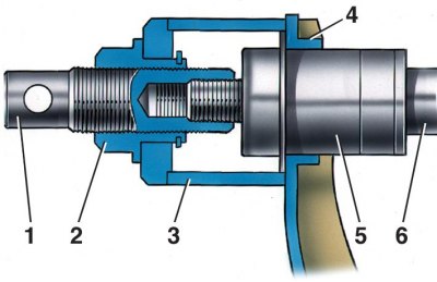
1 - screw; 2 - nut; 3 - glass; 4 - lower lever; 5 - hinge; 6 - the axis of the lower arm
Scheme of pressing the hinge of the lower arm using tool 02.7823.9501
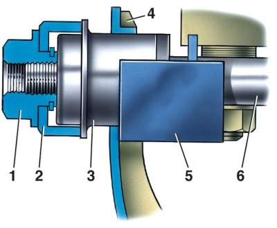
1 - nut; 2 - ring; 3 - hinge; 4 - lower lever; 5 - emphasis; 6 - the axis of the lower arm
Scheme of pressing out the hinge of the upper arm
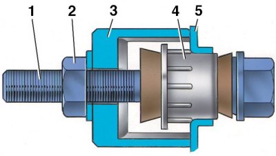
1 - bolt; 2 - nut; 3 - a glass of fixture A.47046; 4 - hinge; 5 - upper lever
Scheme of pressing the hinge of the upper arm
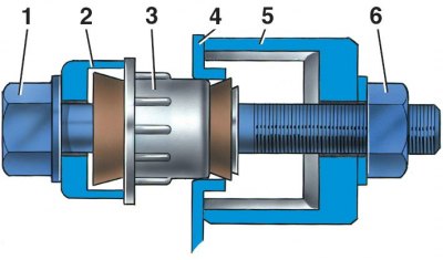
1 - bolt; 2 - ring fixture A.47046; 3 - hinge; 4 - upper lever; 5 - a glass of fixture A.47046; 6 - nut
The need to replace rubber-metal hinges is determined by the signs indicated above, in subsection 6.1.2.
It is possible to replace hinges both directly on the car, and on the levers removed from the car.
Replacement
Rubber-metal joints of the lower arms
1. Place the vehicle on a pit or lift and hang the front of the vehicle from the side where the replacement is to be made.
2. Remove the wheel.
3. Having unscrewed the nut, press out the pin of the spherical joint of the steering rod with the puller A.47052 and take the free end of the side rod back.
4. Loosen the nuts securing the lower suspension arm to the axle and remove the washers from both ends of the axle.
5. Set glass 3 (see fig. Scheme of pressing out the hinge of the lower arm using tool 02.7823.9500) tool 02.7823.9500 on the lever shelf 4 and screw the screw 1 onto the end of the axle 6;
6. Holding the screw 1 with a knob and turning the nut 2, slide the eye of the lever from the outer race of the hinge. Remove the fixture and the pressed hinge 5 from the lever axis.
7. Using a crowbar or a mounting spatula, the lever eye is in a position concentric with the lever axis, insert a new hinge into the hole in the lever eye and put on the axle.
8. Put ring 2 on the end of the axle (see fig. Scheme of pressing the hinge of the lower arm using tool 02.7823.9501) tool 02.7823.9501 and insert stop 5 between shelf 4 and the nearest nut for attaching the axle to the front suspension cross member.
9. Turning the nut 1 and holding the stop 5, press the new hinge 3 into the eye of the lever. Remove the fixture, install the washer and nut securing the lever to the axle. Do not tighten the nut.
10. Similarly, other rubber-metal hinges of the lower suspension arms are replaced.
11. After replacing the joints, connect the tie rod to the steering knuckle arm, tighten and cotter the tie rod ball stud nut, install and secure the wheel.
Rubber mount upper control arms
12. Replace the rubber-metal hinges of the upper suspension arms using tool A.47046 in the same way as on the removed arms (see subsection 6.1.9.3).
13. Unscrew the nut of the upper arm axle and, having removed the axle, turn the arm with the lugs outward.
14. Install cup 3 on the lever (see fig. Scheme of pressing out the hinge of the upper arm) fixtures A.47046 with nut 2 and bolt 1 head inside the lever. Turning nut 2, press out the joint, remove the tool and the joint.
15. Insert a new hinge into the eye of the lever, install the tool A.47046 so that the head of the bolt 1 (see fig. Scheme of pressing the hinge of the upper arm) was directed outward and under the head was the ring 2 of the device A.47046. Turning nut 6, press the hinge and remove the fixture.
16. Similarly, other hinges of the upper arms of the front suspension are replaced.
17. After replacing the hinges, turn the upper arm with the lugs towards the front end, slide it onto the front, insert the upper arm axle, install the axle washer and nut without completely tightening it.
18. Install the wheels, lower the vehicle and tighten the axle nuts. Before tightening the nuts, perform all the operations described above (see subsection 6.1.7).
19. After replacing the rubber-metal joints, make a test drive for 15–20 km and without fail check and, if necessary, adjust the angles of the front wheels.