




Open large image in new tab »
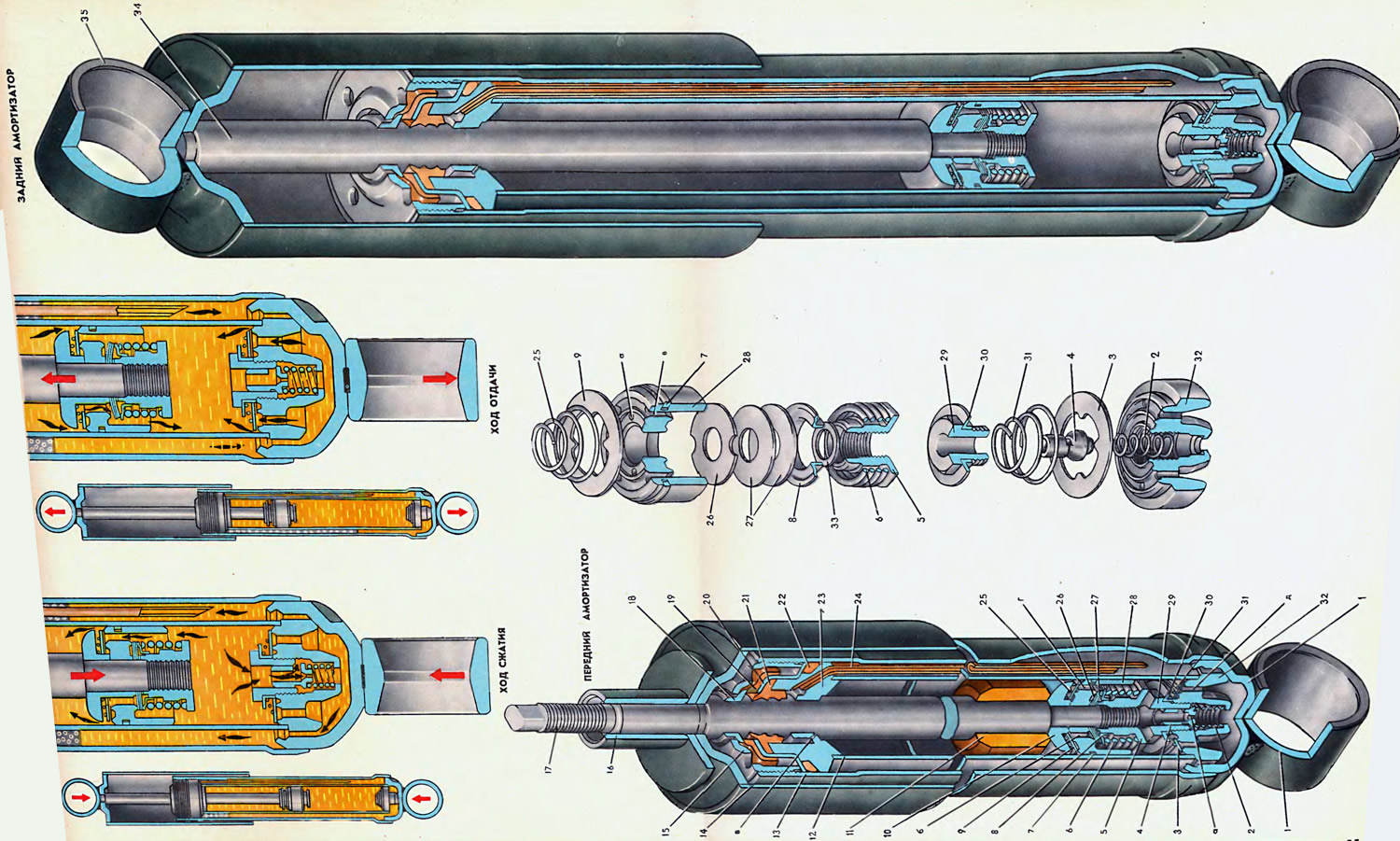
1. Eye. 2. Compression valve spring. 3. Recoil inlet valve. 4. Compression valve. 5. Recoil valve nut. 6. Recoil valve spring. 7. Piston ring. 8. Thrust plate. 9. Bypass valve. 10. Limit plate. 11. Recoil buffer. 12. Slave cylinder. 13. Reservoir. 14. Casing. 15. Reservoir nut. 16. Upper hinge bushing. 17. Front shock absorber rod. 18. Protective ring. 19. Rubber gasket. 20. Oil seal collar. 21. Oil seal. 22. Sealing ring. 23. Guide sleeve. 24. Drain pipe. 25. Bypass valve spring. 26. Throttle disc. 27. Rebound valve disc. 28. Piston. 29. Compression valve seat. 30. Limit plate. 31. Inlet valve spring. 32. Compression valve housing. 33. Rebound valve washer. 34. Rear shock absorber rod. 35. Upper eye. a — throttle hole; b - underwater channel; in - capillary opening; g - bypass channel; d — inlet (8 holes).
Hydraulic shock absorbers installed on the VAZ-2101, VAZ-2102 and VAZ-2103 models are standardized and interchangeable.
The shock absorbers of the front and rear suspensions differ in the lower and upper mount, the operating diagram, the stroke of the rod and some details described below. The shock absorbers are telescopic type, double-acting.
Operating fluid used for filling shock absorbers, MGP-10 according to TU 38-1-01-137-71.
Shock absorber filling capacity, l:
- front - 0.1 20±0.005;
- rear - 0.195±0.005.
The front shock absorber consists of the following main units: a rod assembly with a piston, valves, a guide sleeve with seals, a reservoir nut and a casing; working cylinder; tank assembly with eye; compression valve.
The reservoir 13 of the shock absorber is made of a steel electric-welded pipe. An eye 1 is inserted and welded into the calibrated belt of the lower end of the pipe. The upper end of the reservoir has an internal thread for securing the nut 15. The housing 32 of the compression valve is inserted into the groove in the bottom of the eye 1.
The valve body has a central stepped opening with a thread in the upper part and eight equally spaced around the circumference of the groove holes D for releasing liquid into the cylinder. A seat 29 is screwed into the valve body together with a compression valve 4, which is freely inserted into the central opening of the seat. The valve is pressed by a cone against the chamfer of the seat opening, creating the necessary tightness.
To bypass liquid during a sharp stroke of the piston, a central channel is made in the compression valve with an outlet through a lateral rectangular opening into an annular gap formed by the conical surfaces of the seat and valve.
To throttle the liquid during a quiet piston stroke, a calibrated hole is provided in the compression valve head. The valve is pressed from below by spring 2.
The valve seat with a hexagonal head presses the restrictor plate 30 of the inlet valve, the conical spring 31 and the inlet valve 3.
Inlet valve 3 is a washer with a central shaped hole for centering on the flange of limiting plate 30.
The working cylinder 12 is pressed onto the seating belt of the housing 32 of the compression valve; the inner surface of the cylinder is calibrated. Inside the cylinder, a metal-ceramic piston 28 is installed on the rod 17. The piston has four bypass channels g, evenly spaced in a concentric groove, and four supply holes b, evenly spaced in a concentric groove of a smaller diameter. On the outer surface of the piston, a groove is made, into which a metal-ceramic piston ring 7 is inserted to seal the gap between the piston and the cylinder.
The position of the piston on the rod is fixed by the limiting plate 10 of the bypass valve and the nut 5 of the return valve. The tightening torque of the nut on the rod is 1-1.5 kgf·m.
During assembly, before installing the limiting plate and piston, a polyurethane buffer 11 is installed on the rod, softening the impact of the limiting plate on the guide sleeve during the recoil stroke.
Between the limiting plate and the piston there is a bypass valve 9 and a twisted conical spring 25 pressing it. The bypass valve closes the piston channels g from above.
The holes b are blocked from below by a recoil valve consisting of a pack of disks 26, 27 and a washer 33. Disk 26 is called a throttle. Two opposite cutouts are made along the outer edge of the disk, through which the operating fluid is throttled at low piston speed. The inner edge of the recoil valve is rigidly pressed to the piston by nut 5, and the outer edge is pressed to the piston by copper-plated spring 6 through thrust plate 8. Washer 33 stabilizes the operation of the valve and protects the lower disk from damage by the nut.
The shock absorber rod 17 takes up the axial loads arising from the vibrations of the body and suspension, and moves the piston along the working cylinder. The friction surface of the rod on the guide sleeve 23 and the seal 21 (by the length of the largest diameter) hardened to a high hardness, polished, coated with a layer of chromium and then polished again. High surface finish is necessary to maintain a reliable seal of the rod; chrome plating of the rod increases the wear resistance of its surface.
To guide the rod relative to the working cylinder, a metal-ceramic bushing 23 is used, in which, in addition to the central one, two inclined holes are made: one (c) is a capillary stepped hole for removing air from the working cylinder, the other is for installing a polyethylene drain tube 24. From above, a seal 21 made of petrol- and oil-resistant rubber is installed with a slight tension in the flange of the guide bushing 23.
The guide sleeve 23 is freely installed in the calibrated seat belt of the upper end of the reservoir 13. The upper end of the working cylinder is pressed onto the lower outer groove of the sleeve 23. The junction of the reservoir 13 with the guide sleeve 23 is sealed with a rubber ring 22, pressed from above by the gland collar 20. Between the gland collar and the nut (cover) of the reservoir 13, a rubber gasket 19 and a metal-ceramic protective ring 18 are installed, removing abrasive particles (dirt) from the rod during the compression stroke.
The compression valve body, the working cylinder with the guide sleeve, the sealing ring, the gland housing 20, the gasket 19 and the protective ring 18 are clamped by the nut 15 screwed into the upper end of the reservoir 13. Four holes are made in the nut 15 for tightening with a special key. The tightening torque of the nut 15 is 7-9 kgf·m.
A cover with a casing 14 welded to it and a bushing 16* of the upper shock absorber hinge are pressed onto the upper end of the rod 17 until they stop against the shoulders. A rubber-metal hinge is pressed into the eye 1 of the shock absorber.
The design of the rear shock absorber differs slightly from the design of the front shock absorber: the shock absorber rod does not have an upper threaded end; the mounting eye 35 is directly butt welded to the rod 34; throttle disc 26 instead of two, the front shock absorber disc has six cutouts; the working cylinder is longer, since the piston stroke of the rear shock absorber is greater than that of the front, and accordingly the reservoir and drain pipe are longer; the spring of the 6th rebound valve is softer in characteristics than the similar spring of the front shock absorber and, unlike it, is not copper-plated.
(The original is on the portal: «VAZbook.ru»)
The 11th recoil buffer is not installed on the 34th rod of the rear shock absorber.
Operation of the shock absorber. The working cylinder with the piston and the reservoir body form three cavities in the shock absorber: the upper (in the working cylinder above the piston), must be constantly filled with operating fluid; lower (in the working cylinder under the piston), constantly filled with operating fluid; the cavity between the working cylinder and the tank body contains a reserve amount of operating fluid and air.
Compression stroke. Under the influence of compressive forces, the piston moves downwards. The liquid under the piston lifts the bypass valve 9 and flows through channels g into the upper cavity. Part of the liquid, equal in volume to the inserted rod, flows through the compression valve 4 into the reservoir. At low piston speed, the pressure is insufficient to overcome the resistance of spring 2 and the liquid is throttled through opening a of the compression valve. At high piston speed, the liquid does not have time to flow through the throttle opening. The pressure in the working cylinder increases, as a result of which the compression valve opens and releases liquid into the reservoir, relieving excess pressure.
During the compression stroke, the damping effect is exerted only by throttling the volume of liquid through the compression valve, equal to the volume of the inserted rod.
The flow of liquid through the piston bypass holes has almost no braking effect.
Recoil stroke. When the shock absorber is stretched, the piston begins to move upward and exerts pressure on the liquid in the upper cavity. The bypass valve 9 closes. The liquid begins to flow from the upper cavity to the lower one.
At low piston speed, the liquid supplied through the shaped cutouts (by inner diameter) bypass valve 9 and piston hole 6 are throttled through constantly open throttle slots formed by cutouts on throttle disk 26, thereby creating rebound resistance.
At high piston speeds, the fluid pressure increases so much that the return valve discs bend and the main flow of fluid flows through the resulting annular gap between the throttle disc and the piston, releasing excess pressure.
The volume of liquid in the upper cavity of the working cylinder is less than the volume of liquid in the lower cavity by the volume of the rod leaving the cylinder. Therefore, the missing volume of liquid enters the lower cavity under the suction action of the piston and the air pressure in the reservoir through the holes d, overcoming the resistance of the spring 31 and opening the inlet valve 3.
The resistance of the recoil stroke is several times greater than the resistance of the compression stroke and is achieved by selecting the appropriate structural elements of the shock absorbers. This is necessary to reduce the impact of shocks on the car body that occur when a wheel hits a road obstacle.
When the car is parked, air and liquid vapor accumulate in the shock absorber cylinder. To remove them from the cylinder in order to speed up the shock absorber's activation, a capillary hole in the guide bushing and drain pipe 24 are used. Air suction into the upper cavity of the working cylinder through the capillary hole is reduced to a minimum, since the end of the drain pipe is completely immersed in the operating fluid.