
English Русский
Български
Беларускі
Український
Српски
Hrvatski
Română
Polski
Slovenský
Magyar
| Articles | Contacts | Sitemap |   
Repair and maintenance Lada Repair and maintenance Mazda Repair and maintenance Mitsubishi Repair and maintenance Toyota Repair and maintenance Land Rover Repair and maintenance Hyundai Repair and maintenance Nissan
VAZbook.ru


Main     1111   2101   2105   2106   2107   2109   2110   2115   2121  
VAZ-2104 (1984-2012) VAZ-2105 (1979-2010) VAZ-21051 (1979-2010)
  • Main
  • «Zhiguli»
  • VAZ-21051
  • Power unit
  • Power and exhaust system
  • Disassembly and assembly of carburetor 21051-1107010

Disassembly and assembly of carburetor 21051-1107010 (VAZ-21051)

            0

Carburetor Cover Parts 21051-1107010
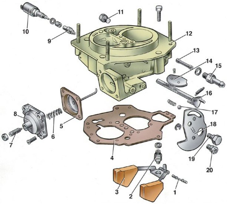


1 – float axis; 2 – needle valve; 3 – float; 4 – gasket; 5 – diaphragm of the starting device with…

1 – float axis; 2 – needle valve; 3 – float; 4 – gasket; 5 – diaphragm of the starting device with a rod; 6 – spring; 7 – adjusting screw; 8 – Starter cover; 9 – idle fuel jet; 10 – electromagnetic shut-off valve; 11 – cork; 12 – carburetor cover; 13 – fuel filter; 14 – air damper; 15 – fuel supply pipe; 16 – air damper shaft with lever; 17 – air damper control lever locking ball; 18 – air damper control lever; 19 – lever axis; 20 – air damper drive rod mounting bushing


Carburetor body parts 21051-1107010
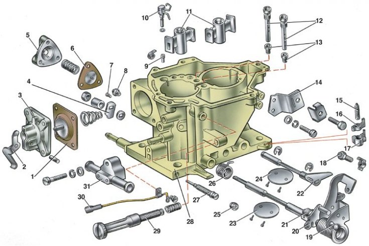


1 – accelerator pump diaphragm; 2 – accelerator pump drive lever; 3 – lid; 4 – accelerator pump…

1 – accelerator pump diaphragm; 2 – accelerator pump drive lever; 3 – lid; 4 – accelerator pump drive cam; 5 – power mode economizer cover; 6 – economizer diaphragm; 7 – fuel jet of economizer; 8 – economizer valve; 9 – accelerator pump check valve; 10 – accelerator pump nozzles with fuel supply valve; 11 – Sprayers; 12 – main air jets with emulsion tubes; 13 – main fuel jets; 14 – bracket for fastening the air damper drive rod casing; 15 – adjusting screw of the second chamber; 16 – adjusting screw stopper; 17 – stopper cap; 18 – first chamber throttle valve opening adjusting screw; 19 – first chamber throttle shaft with drive levers; 20 – second chamber locking lever; 21 – locking lever spring; 22 – second chamber throttle shaft with lever; 23 – first chamber throttle valve; 24 – second chamber throttle valve; 25 – plug for adjusting screw of mixture quality (composition); 26 – return spring of the second chamber throttle actuator lever; 27 – adjusting screw for idle mixture quality (composition); 28 – carburetor body; 29 – idle mixture quantity adjusting screw; 30 – electric wire of the forced idle economizer limit switch; 31 – carburetor heating unit


1. Loosen the carburetor cover mounting screws and remove it carefully so as not to damage the gasket and float.

2. Disassemble the carburetor cover:
  • using a mandrel, carefully push out axis 1 (see fig. Carburetor cover parts 21051-1107010) float 3 from the racks and, without damaging the float tongues, remove it;
  • remove gasket 4 of the cover, unscrew the seat of the needle valve 2, unscrew the fuel supply pipe 15 and remove the fuel filter 13;
  • unscrew the electromagnetic shut-off valve 10 and remove the jet 9;
  • unscrew the axle 19, remove the air damper control lever 18, disconnect the air damper control lever spring. If necessary, unscrew the air damper screws, remove the damper 14 and axle 16;
  • disassemble the diaphragm starter by removing cover 8 of the starter assembly with adjusting screw 7. Remove spring 6 and diaphragm 5 with rod.

3. Disassemble the carburetor body (see fig. Carburetor body parts 21051-1107010) to do this, perform the following operations:
  • remove cover 3 of the accelerator pump with lever 2 and diaphragm 1;
  • remove the nozzles 10 of the accelerator pump and the nozzles 11 of the first and second chambers;
  • unscrew the nut of the first chamber throttle shaft, remove cam 4 of the accelerator pump drive and washer;
  • unscrew the idle mixture quantity adjusting screw 29;
  • having broken the plastic plug 25, unscrew the adjusting screw 27 of the quality (composition) of the idle mixture;
  • remove cover 5 of the power mode economizer, diaphragm 6 and spring;
  • unscrew the fuel jet 7 of the power mode economizer, the main air jets 12 with emulsion tubes and the main fuel jets 13 of the main metering systems.

4. If necessary, unscrew the mounting screws of the throttle valve 23 of the first chamber, remove the valve and take out the axle 19 together with the drive levers. After removing the lock washer and unscrewing the mounting screws, remove the throttle valve 24 of the second chamber and take out the axle 22 of the valve.

5. Assemble the carburetor in the reverse order. When tightening the throttle valve mounting screws, peal the screws along the contour using a special device to prevent deformation of the valve axes.


This article is available at russian, bulgarian, belarusian, ukrainian, serbian, croatian, romanian, polish, slovak, hungarian
The text was reviewed by the specialist: Grigory Vologodtsev

Share with friends:

Previous articles
VAZ-21051: Power and exhaust system
Next articles

Removal and installation of carburetor 21051-1107010
Calibration data for carburetor 21051-1107010
Carburetor 21051-1107010 — design description
Checking the performance of the forced-run economizer
Adjustments and checks of the carburetor after assembly
Carburetor adjustment 21051-1107010
Exhaust gas system

More articles from other manuals on VAZ cars:
➠ Description of operation of carburetor 2107-1107010-20 VAZ-2106 (1976-2006)
➠ Scheme of the device and operation of the carburetor… VAZ-21214 (1994-2006)
➠ Air filter, carburetor drive, mufflers VAZ-1111 (1988-1996)
➠ Carburetor device VAZ-2101 (1970-1983)
➠ Carburetor Engine Intake Manifold and Exhaust Manifold Gaskets —… VAZ-2107 (1982-2012)
Link in different formats to this page


Visitor comments

No comments yet


How much will 35 + 20 ?


VAZ-2104 (1984-2012) 
  • General information
  • Operation and maintenance
  • Power unit
  • Engine repair
  • Fuel system (carburetor)
  • Fuel system (injector)
  • Control system
  • Cooling system
  • Exhaust system
  • Transmission
  • Clutch
  • Car gearbox
  • Cardan gear
  • Rear axle
  • Chassis
  • Front suspension
  • Rear suspension
  • Wheels and tires
  • Steering
  • Brake system
  • Body
  • Exterior
  • Interior
  • Doors and glass
  • Ventilation and heating
  • Electrical equipment
  • Equipment and devices
  • Headlights and lighting
  • Engine electrics
  • Electrical circuits


VAZ-2105 (1979-2010) 
  • General information
  • Vehicle description
  • Vehicle device
  • Vehicle operation
  • Maintenance
  • Power unit
  • Engine repair
  • Cooling and lubrication system
  • Supply system
  • Transmission
  • Clutch
  • Car gearbox
  • Cardan gear
  • Rear axle
  • Chassis
  • Suspension and shock absorbers
  • Steering
  • Brake system
  • Body
  • Body elements
  • Electrical equipment
  • Engine electrics
  • Equipment and devices


VAZ-21051 (1979-2010) 
  • General information
  • Introduction to guide
  • User manual
  • Troubleshooting
  • Power unit
  • Engine repair
  • Engine repair VAZ-2103
  • Cooling system
  • Lubrication system
  • Power and exhaust system
  • Fuel injection
  • Transmission
  • Clutch
  • Car gearbox
  • Cardan gear
  • Rear axle
  • Chassis
  • Suspension and shock absorbers
  • Steering
  • Brake system
  • Body
  • Exterior
  • Interior
  • Doors and windows
  • Electrical equipment
  • Equipment and devices
  • Engine electrics
  • Ignition system
  • Electrical circuits


VAZbook.ru © 2017 · Mobile version · Contact with administration · Sitemap: EN BG BY UA RS HR RO PL SK HU · Site search · News and articles VAZ-1111 · VAZ-11113 · VAZ-2101 · VAZ-21011 · VAZ-2104 · VAZ-2105 · VAZ-21051 · VAZ-2106 · VAZ-21061 · VAZ-2107 · VAZ-21099 · VAZ-2109 · VAZ-2108 · VAZ-2110 · VAZ-2112 · VAZ-2114 · VAZ-2115 · VAZ-2121 · VAZ-21213 · VAZ-21214 ·
The site stores technical data using cookies to improve the service.