
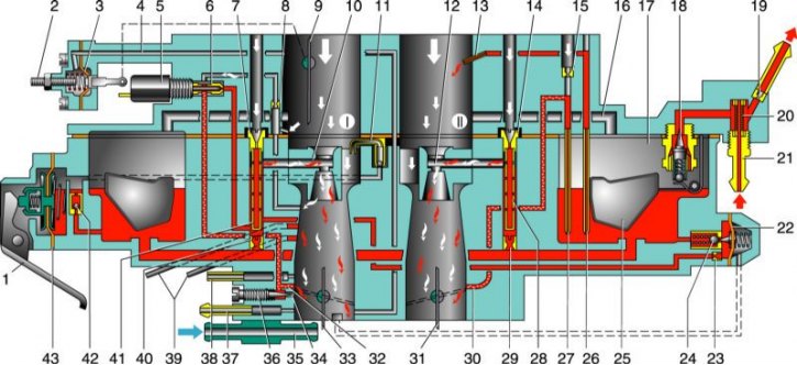
I - the first chamber; II - the second chamber; 1 – accelerator pump drive lever; 2 - adjusting screw of the starting device; 3 - aperture of the starting device; 4 - air channel of the starting device; 5 - electromagnetic shut-off valve; 6 - idle fuel jet; 7 - the main air jet of the first chamber; 8 - idle air jet; 9 - air damper; 10 - atomizer of the main dosing system of the first chamber; 11 - accelerator pump sprayer; 12 - atomizer of the main dosing system of the second chamber; 13 – econostat atomizer; 14 - the main air jet of the second chamber; 15 - air jet of the transition system of the second chamber; 16 - balancing channel of the float chamber; 17 - float chamber; 18 - needle valve; 19 - calibrated hole for bypassing fuel into the tank; 20 – carburetor fuel filter; 21 - fuel supply fitting; 22 - diaphragm economizer power modes; 23 - fuel jet economizer power modes; 24 - ball valve of the economizer of power modes; 25 - float; 26 - econostat fuel jet with a tube; 27 - fuel jet of the transition system of the second chamber with a tube; 28 - emulsion tube of the second chamber; 29 - the main fuel jet of the second chamber; 30 - outlet of the transition system of the second chamber; 31, 33 - throttle valves; 32 – slot of the transition system of the first chamber; 34 - the outlet of the idle system; 35 - carburetor heating block; 36 - composition adjusting screw (quality) idle mixtures; 37 - crankcase ventilation fitting; 38 - fitting for supplying vacuum to the vacuum ignition regulator; 39 - vacuum extraction fittings for the recirculation system; 40 - main fuel jet of the first chamber; 41 - emulsion tube of the first chamber; 42 - ball valve of the accelerator pump; 43 - accelerator pump diaphragm.
To prepare the air-fuel mixture of the required composition (depending on the operating mode of the engine) serves as a carburetor 21073-1107010 - emulsion type, two-chamber, with a falling flow, with sequential forced opening of the throttle valves. Throttle valve drive - mechanical, lever. The carburetor has a balanced float chamber, a crankcase exhaust system, heating of the throttle valve zone of the first chamber, a starting device with a mechanical drive, and an idle speed solenoid shut-off valve. To start a cold engine, an air damper with a mechanical cable drive and a vacuum starting device is installed above the first chamber.
Fuel is supplied to the carburetor float chamber through a strainer mounted behind the inlet fitting. Float chamber - two-section (this design reduces the effect of fluctuations in fuel level on engine performance during turns and rolls of the car). The specified fuel level in it is maintained by a needle valve. From the float chamber, fuel enters through the main fuel jets (first and second chambers) into emulsion wells, where it mixes with air passing through calibrated holes in the top of the emulsion tubes (main air jets). Then, through the atomizers, the air-fuel emulsion enters the small and large diffusers of the carburetor.
The idle system takes fuel from the emulsion well after the main fuel jet of the first chamber. Fuel flows through the idle jet (structurally integrated with the idle air shutoff solenoid valve), after which it mixes with air from the channel from the idle air jet and from the expanding part of the diffuser (for stable operation during the transition to idling). The resulting emulsion is fed under the throttle valve through a hole blocked by a quality screw. Screw Quantity (speed) regulates the opening of the throttle valve of the first chamber at idle.
With partial opening of the throttle valve of the first chamber (before switching on the main dosing system) the air-fuel mixture enters the chamber through a vertical slot located at the level of the throttle in the closed position; when the throttle valve of the second chamber is partially opened, through the hole located just above the throttle valve of the second chamber in the closed position.
The power mode economizer comes into operation with a significant opening of the throttle valves. Fuel is taken from the float chamber through a ball valve. As long as the economizer diaphragm is held by vacuum in the intake manifold, the valve is closed. When the throttle valves open, the vacuum behind them drops, and the pusher, riveted to the diaphragm, releases the valve. In this case, the fuel enters through the economizer jet into the emulsion well, bypassing the main fuel jet, enriching the mixture.
Econostat provides additional fuel supply directly from the float chamber (through the econostat jet and tube system) into the second chamber. The econostat is switched on at maximum power modes, further enriching the working mixture.
The accelerator pump is a diaphragm type, mechanically driven from the throttle valve axis of the first chamber through a profile cam. When the throttle is opened, the cam acts on the lever, which in turn acts on the diaphragm.
A portion of fuel is injected through the atomizer into the first chamber of the carburetor, enriching the combustible mixture in acceleration modes. The pump is equipped with two ball valves: the check valve is located in the channel connecting the float chamber with the cavity of the accelerating pump; it opens when it is filled with fuel (pedal «gas» released and the return spring pushes the diaphragm back) and closes when fuel is injected. Another valve is located in the atomizer; it opens under the pressure of the injected fuel and closes under its own weight as soon as the fuel supply is stopped. This prevents fuel from flowing out of the channels and air leaks. The pump performance is determined by the cam profile.
The starting device is used to enrich the air-fuel mixture when starting a cold engine. It is controlled from the driver's seat with a handle «suction», through a rope. When the handle is pulled out to the stop, the three-arm air damper control lever, turning on the axis, acts on the air damper lever with a profile cutout, closing it. At the same time, the outer profile (in the lower part) it acts on the throttle control lever of the first chamber, slightly opening it to the starting gap C (its value is adjusted by a screw on the lever).
After the engine starts, the vacuum in the intake manifold increases and is transferred to the cavity of the starting device. Under the action of rarefaction, the diaphragm of the starting device, overcoming the resistance of the return spring, slightly opens the air damper through the rod to the starting clearance B (its value is regulated by a screw on the starter cover). When the air damper control handle is sunk, clearances C and B decrease, their value with a partially recessed handle depends on the profiles of the three-arm lever (its cutout and outer profile) and cannot be adjusted. If the choke control knob is pulled out, then when you press the pedal «gas» only the throttle valve of the first chamber will open, since the throttle valve of the second chamber is blocked by a special lever mounted on the throttle actuator lever. This prevents jerks and dips when driving with a cold engine (with the choke control handle pulled out).
The forced idle economizer consists of a limit switch, an electromagnetic shut-off valve and a control unit. The solenoid valve shuts off the fuel supply to the idle system and the transition system of the first chamber. Normal valve condition (no voltage applied) - closed. It opens when you press the pedal «gas», as well as at the number of revolutions of the crankshaft 1900 min–1 and below. The valve closes if the pedal «gas» released (limit switch shorted to ground) and engine speed exceeds 2100 min-1, as well as when the ignition is turned off, which prevents the engine from running when the ignition is off (dieseling).
The mixture prepared in the carburetor enters the engine cylinders through the intake manifold. It is cast from aluminum alloy and is attached to the engine with studs through heat-resistant gaskets.
Carburetor calibration data 21073-1107010
|
Options |
First chamber
|
Second chamber
|
| Mixing chamber diameter, mm |
32
|
32
|
| Diffuser diameter, mm |
24
|
24
|
| Sprayer marking |
7
|
6
|
| Main dosing system:
|
||
|
107,5
|
117,5
|
|
150
|
135
|
| Type of emulsion tube |
ZD
|
ZC
|
| Idling system of the first chamber and transition system of the second chamber:
|
||
|
39
|
70
|
|
140
|
140
|
| Econostat:
|
||
| conditional consumption of the fuel jet |
—
|
70
|
| Power mode economizer:
|
||
|
40
|
—
|
|
1,5±10%
|
—
|
| Accelerator pump:
|
||
|
45
|
—
|
|
14
|
—
|
|
4
|
—
|
| Start clearances: | ||
|
3,0
|
—
|
|
1,1
|
—
|
| Hole diameter for vacuum corrector, mm |
1,2
|
—
|
| Needle valve hole diameter, mm |
1,8
|
|
| Diameter of the fuel bypass hole in the tank, mm |
0,70
|
|
| Engine crankcase ventilation hole diameter, mm |
1,5
|
—
|