
View of the carburetor 21051-1107010 from the throttle actuator side
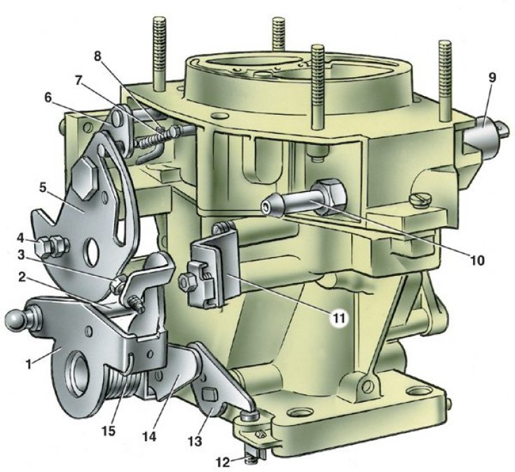
1 - throttle actuator lever; 2 – pin of the locking lever of the second chamber; 3 - adjusting screw for slightly opening the throttle valve of the first chamber; 4 - screw for fastening the air damper drive rod; 5 - air damper control lever; 6 - air damper lever; 7 - air damper return spring; 8 – a rod of a diaphragm of the starting device; 9 - electromagnetic shut-off valve; 10 - fuel supply pipe; 11 – an arm of fastening of a cover of draft of a drive of an air damper; 12 - adjusting screw of the second chamber; 13 - throttle lever of the second chamber; 14 – throttle actuator lever of the second chamber; 15 - throttle return spring of the first chamber
On VAZ-2105 vehicles since 1986, carburetors of a different design, model 21051-1107010, can be installed. Carburetor emulsion type, two-chamber, with sequential opening of throttle valves.
The carburetor has a balanced float chamber, a crankcase exhaust system for the throttle valve, and a blocking of the second chamber.
Scheme of the main dosing systems of the carburetor 21051-1107010
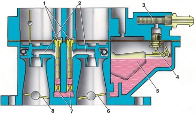
1 - main air jets with emulsion tubes; 2 – atomizers of the first and second chambers; 3 - fuel filter; 4 - needle valve; 5 - float; 6 - throttle valve of the second chamber; 7 - main fuel jets; 8 - throttle valve of the first chamber
Scheme of the econostat and economizer of the power modes of the carburetor 21051-1107010
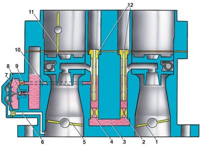
1 - throttle valve of the second chamber; 2 - the main fuel jet of the second chamber; 3 - fuel channel from the float chamber; 4 - the main fuel jet of the first chamber; 5 - throttle valve of the first chamber; 6 – vacuum supply channel; 7 – economizer diaphragm; 8 - ball valve; 9 – economizer fuel jet; 10 - fuel channel; 11 - air damper; 12 - main air jets
Carburetor accelerator pump diagram 21051-1107010
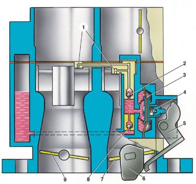
1 - sprayers; 2 - ball valve for fuel supply; 3 - pump diaphragm; 4 - pusher; 5 – drive lever; 6 - pump drive cam; 7 - throttle valve of the first chamber; 8 - check ball valve; 9 - throttle valve of the second chamber
Carburetor starter 21051-1107010
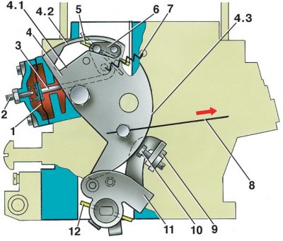
1 - diaphragm; 2 - adjusting screw; 3 - diaphragm rod; 4 – air damper control lever; 4.1 - the lower profile of the groove of the lever 4 to limit the maximum opening of the air damper; 4.2 - the upper profile of the groove, which provides mechanical opening of the air damper; 4.3 - the edge of the lever to ensure the starting clearance of the throttle valve of the first chamber; 5 - air damper; 6 - air damper lever; 7 - air damper return spring; 8 – draft of a drive of an air damper; 9 - stopper of the adjusting screw; 10 - adjusting screw for slightly opening the throttle valve of the first chamber; 11 - throttle actuator lever; 12 - throttle valve of the first chamber
The carburetor has the main dosing systems of the first and second chambers, the idle system of the first chamber with a transition system, the transition system of the second chamber, forced idle economizer, power mode economizer, econostat, diaphragm accelerator pump, starting device.
Calibration data for the carburetor are shown in the table Carburetor calibration data 21051-1107010.