
Carburetor Throttle Adjustment 2105-1107010
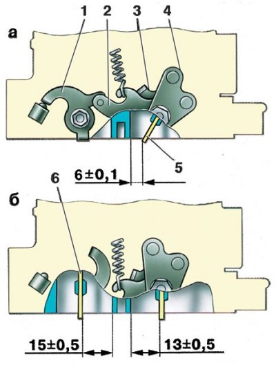
a - partial opening of the throttle valve of the first chamber; b - full opening of the throttle valves; 1 - lever on the axis of the throttle valve of the second chamber; 2 - a lever that limits the opening of the throttle valve of the second chamber; 3 - a lever rigidly connected to the axis of the throttle valve of the first chamber; 4 – damper drive lever; 5 - throttle valve of the first chamber; 6 - throttle valve of the second chamber
Throttle position
Partial opening of the throttle valve of the first chamber, in which the upper antennae of the lever 3 (drawing a) is in contact with lever 2, should be 6±0.1 mm.
This size can be adjusted by bending the upper antennae of the lever 3.
The full opening of the throttle valves is checked by turning the levers of their drive to the position against the stop. The value of the maximum opening of the throttle valve of the first chamber (13±0.5mm) adjustable by bending the lower end of the lever 3.
The value of the maximum opening of the throttle valve of the second chamber (15±0.5 mm) adjustable by screwing in or unscrewing the pneumatic drive rod.
Adjusting the position of the microswitch
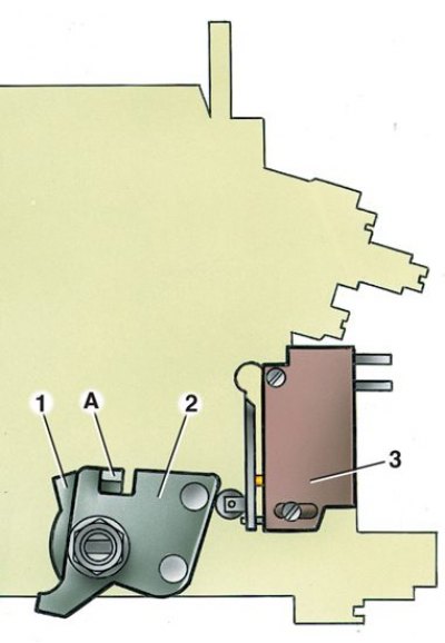
1 - a lever fixed on the axis of the throttle valve of the first chamber; 2 - throttle actuator lever; 3 - microswitch; A - antennae of the lever 1
Microswitch position
The position of the microswitch is adjusted with the air damper open. Microswitch 3 should turn off when lever 2 is turned clockwise until it stops. When lever 2 is turned counterclockwise from its initial position until it stops against the barb A of lever 1, the microswitch should turn on.
To adjust the moment of turning on and off the microswitch, loosen the screws securing it to the bracket and turn it relative to the top screw to the required position. Then tighten the fixing screws.
Carburetor starter drive adjustment 2105-1107010
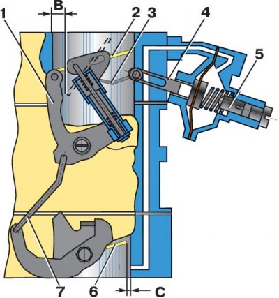
1 - three-arm air damper drive lever; 2 - air damper; 3 - thrust of the starting device; 4 - stock; 5 - adjusting screw; 6 - throttle valve of the first chamber; 7 – draft of a drive throttle
Starting device
When turning lever 1 counterclockwise to the stop, the air damper must be completely closed. Moreover, in this position of the lever, the end of the rod 3 must be at the end of the groove of the rod 4 of the starting device, but do not move the rod. This requirement is fulfilled by bending the rod 3.
When the air damper is fully closed, the throttle valve of the first chamber should be ajar by 0.7–0.8 mm (gap C - the distance between the damper and the chamber wall at the location of the vias of the idle system).
This gap is adjusted by bending the rod 7.
Fully closed choke should open 50.5 mm (clearance B) the rod of the starting device when moving it manually to the right until it stops. This value is adjusted by screw 5.
Fuel supply by accelerator pump
The fuel supply of the accelerator pump is checked for ten full strokes (turns) lever 4 (see fig. Carburetor Throttle Adjustment 2105-1107010) throttle actuators.
The fuel that comes out of the pump nozzle during these ten strokes is collected in a beaker. Its volume should be 5.25–8.75 cm3.
Before starting the test, make ten trial strokes with the lever to fill the channels of the accelerator pump.
Needle valve tightness
The tightness of the needle valve is checked on a stand that supplies fuel to the carburetor at a pressure of 30 kPa (3 mm w.c. Art.). After setting the fuel level in the test tube of the stand, its fall is not allowed for 10–15 s. If the level of fuel in the vial drops, this indicates a fuel leak through the needle valve.