
Steering elements
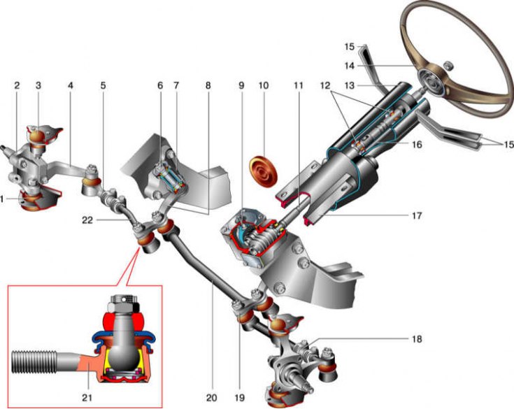
1 - lower ball joint; 2 – rotary fist; 3 - upper ball joint; 4 – the lever of a rotary fist; 5 – a tip of steering draft; 6 - the axis of the pendulum lever; 7 – pendulum arm bracket; 8 - pendulum lever; 9 – a reducer of the steering mechanism; 10 - shaft seal; 11 - steering shaft; 12 - needle bearings of the upper shaft; 13 - facing casing; 14 - steering wheel; 15 - steering column switches; 16 - bracket pipe; 17 – an arm of a steering shaft; 18 - adjusting clutch; 19 – steering arm; 20 - medium thrust; 21 - steering tip with a hinge in the section; 22 - lateral thrust.
Design Description
The steering consists of a steering mechanism and a steering gear.
The steering mechanism includes a steering wheel, a steering shaft, a worm gear and fastening parts.
The steering wheel is secured with a nut to the upper splined end of the steering shaft. The wheel has a sound signal switch, covered with a plastic cover.
The lower part of the steering shaft is connected to the splined end of the gearbox shaft with a splined tip and a pinch bolt. The upper part of the steering shaft rotates in needle bearings fixed in the shaft mounting bracket. The steering wheel switches are mounted on a plastic sleeve.
The steering shaft bracket is secured to the body with two nuts and two shear head screws. An ignition switch with a locking mechanism is installed in the bracket socket.
The design of the bracket allows you to change the vertical inclination of the shaft to compensate for the misalignment of the steering shaft and the worm shaft.
The bracket and the upper part of the steering shaft are covered with plastic casings.
The steering gear housing is secured with three bolts to the left side member of the body inside the engine compartment.
Washers are installed between the crankcase and the spar, the selection of the thickness of which regulates the horizontal deviations of the steering shaft and the worm shaft.
A worm is installed in the gearbox housing on two collapsible ball bearings, which engages with the bipod shaft roller.
The axial clearance in the bearings is regulated by the selection of gaskets between the crankcase and the cover.
The bipod shaft rotates in two bronze bushings pressed into the crankcase. A double-ridged roller is installed at the upper end of the bipod shaft, and a bipod of the steering mechanism is installed on the lower end, on conical splines. The depth of engagement of the roller with the worm is regulated by a screw installed in the top cover of the crankcase.
The steering drive consists of three rods, a bipod, a pendulum arm bracket and trunnion pivot arms.
At the ends of the one-piece middle link, ball joints are installed for connection with the pendulum lever and the steering mechanism bipod. The side rods are split, they consist of two parts connected to each other by a threaded coupling. Couplings are fixed on rods with coupling collars. When the threaded coupling rotates, the length of the rod changes and, accordingly, the toe-in of the vehicle's wheels.
In the ends of the rods, ball joints are installed for connection with the levers of the pivot pins, the bipod of the steering mechanism and the pendulum lever.
The pendulum arm bracket is fixed with two bolts on the right side member of the body, in the engine compartment. Two plastic bushings are installed in the bracket, in which the lever axis rotates.
The angle of rotation of the wheels is limited by two stops on the bipod, which, at maximum turns of the steering wheel, rest against the gearbox housing.