
The steering wheel is mounted on the splines of the upper shaft of the steering column and fixed with a self-locking nut.
The steering column consists of the upper and intermediate steering shafts connected by a cardan joint and their mounting bracket. The upper steering shaft rotates in two bearings pressed into the bracket tube. An ignition lock with an anti-theft device is installed on the bracket pipe.
The pipe has the ability to move in the longitudinal and vertical direction relative to the bracket itself, after which it is fixed in the selected position with a coupling bolt, on which
installed adjusting sleeve with lever. By lowering the lever, you can change the height of the steering wheel. Raising the lever locks the wheel in the selected position. The front end of the steering column bracket is attached to the body with tear-off bolts and special fixing plates. The bolts are tightened until the heads break off. This prevents them from turning away and replacing the steering column along with the ignition switch when trying to steal a car. The safety of the steering column is provided by special fixing plates. In a frontal impact, the plates deform and no longer hold the front of the steering column bracket, allowing it to drop down. This moves the steering column to a vertical position and moves the steering wheel away from the driver.
The intermediate steering shaft is connected to the steering mechanism through a rubber elastic coupling, which allows for slight misalignment of the input shaft and the lower shaft of the steering column.
The steering mechanism is rack and pinion type, consists of a crankcase, drive gear and steering rack, which are in gearing. The steering mechanism is attached to the engine shield with two rubber supports, two clamps and four bolts with nuts. When the steering wheel is turned, rotation is transmitted through the upper and intermediate shafts of the steering column to the drive gear, which, turning, moves the rack.
Tie rods consist of the actual steering rods, tips and threaded inserts connecting the steering rods and tips. Ball pins are installed in the tie rod ends.
One end through the silent block (rubber-metal joint) steering rods are attached to the steering rack of the steering mechanism, and with tips, using ball pins, to the swing arms of the front suspension shock absorber struts. When the steering rack is moved, the rods turn the front suspension struts on which the drive wheels are mounted.
The length of the steering rods can be adjusted by rotating the threaded inserts and thereby changing the toe of the front wheels.
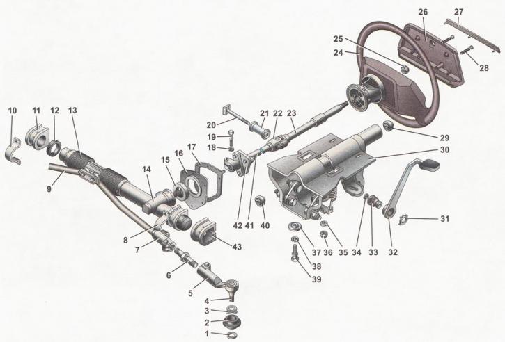
Steering device diagram: 1 - sealing ring; 2 - protective cover of the tie rod end; 3 - spring ring; 4 - ball pin; 5 - tie rod end; 6 - threaded insert; 7 - left steering rod; 8, 10 - brackets for fastening the steering mechanism; 9 - right steering rod; 11 - right support of the steering mechanism; 12 - spacer ring; 13 - protective cover of the steering mechanism; 14 - steering mechanism; 15 - sealant; 16 - thrust plate; 17 - gasket; 18 - spring washer; 19 - bolt; 20 - coupling bolt; 21 - spacer sleeve; 22 - universal joint; 23 - upper steering shaft; 24 - steering wheel; 25 - steering wheel nut; 26 - steering wheel pad; 27 - decorative overlay; 28 - self-tapping screw, 29, 40 - bearings; 30 - bracket for mounting the upper steering shaft; 31 - retaining ring; 32 - lever for adjusting the position of the steering column; 33 - adjusting sleeve; 34, 35 - washers; 36 - self-locking nut; 37 - fixing plate; 38 - spring washer, 39 - special bolt with a detachable head; 41 - intermediate steering shaft; 42 - rubber elastic coupling; 43 - left steering gear support