
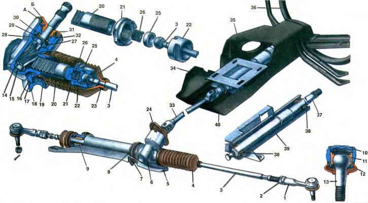
1. Outer tie rod end. 2. Locknut. 3. Inner tie rod end. 4. Protective case. 5. Steering gear support. 6. Carter of the steering mechanism. 7. Collar of fastening of the steering mechanism. 8. Rubber cushion. 9. Rail bushing. 10. Support washer. 11. Ball pin insert. 12. Protective cap. 13. Ball joint pin. 14. Roller bearing. 15. Drive gear. 16. Reiki stop. 17. Sealing ring stop. 18. Stop nut. 19. Retaining ring nut. 20. Rake. 21. Locknut. 22. Ball joint. 23. Clamp cover. 24. Shaft seal. 25. Thrust stop. 26. Stop spring. 27. Ball bearing. 28. Retaining ring. 29. Protective washer. 30. O-ring. 31. Anther. 32. Bearing fastening nut. 33. Intermediate cardan shaft. 34. Bracket for mounting the steering shaft. 35. Top facing casing. 36. Steering wheel. 37. Steering column shaft. 38. Steering column shaft bearing. 39. Bracket pipe. 40. Lower facing casing.
A and B - marks on the crankcase of the steering mechanism and on the anther
Front-wheel drive vehicles carry more load on the front wheels than rear-wheel drive models. The front wheels are not only guiding, but also leading. As a result, more force is required to turn them. Therefore, these vehicles use rack and pinion steering, which has a larger gear ratio and higher efficiency. This type of steering is compact and simple in design, more economical to manufacture and goes well with the front-wheel drive layout and the transverse arrangement of the power unit «gear - rack», with fastening of the steering gear rods to the ends of the rack.
The steering mechanism is mounted on a support 5 with two clamps 7 in the engine compartment, which allows more rational use of the space inside the body. Support 5 of the steering mechanism, in turn, is attached to the subframe, on which the power unit, front suspension and front wheel brakes are also mounted. To dampen vibrations, rubber pads 8 are installed under the brackets of the clamps for fastening the steering mechanism.
The crankcase 6 of the steering mechanism is cast from aluminum alloy together with the supports. In the cavity of the crankcase, a drive gear wheel 15 is installed on two bearings. The lower bearing 14 is roller bearing, with a separator and a stamped outer race. pressed into the steering box. The upper ball bearing 27 with a plastic separator is pressed onto the shaft of the gear wheel 15 and is fixed on it with a retaining ring 28. The outer race of this bearing is located in the housing of the crankcase and is fixed with a nut 32 with an external thread. The nut is locked with a special toothed washer. The gap between the gear shaft and the hole in the nut 32 is sealed with a rubber O-ring 30. The protective plastic washer 29, mounted on the gear shaft, prevents the rubber ring 30 from slipping onto the bearing circlip 28.
The cavity of the crankcase of the steering mechanism is protected from contamination by anther 31, which is mounted on the shaft of the drive gear and is tightly pressed against the end of the crankcase of the steering mechanism. The anther is fixed on the gear shaft with a wire ring. Marks A and B are made on the crankcase of the steering mechanism and on the anther for the correct assembly of the steering mechanism.
Splines are cut on the drive gear shaft and an annular groove is machined for attaching the universal joint yoke of the intermediate shaft 33. The fork coupling bolt passes through the annular groove of the shaft, excluding their separation.
The rack 20 is engaged with the teeth of the drive gear. With its cylindrical part, it rests on the plastic sleeve 9. The rack sleeve is installed on the right side of the crankcase in a cylindrical bore; To eliminate the gap between the bushing and the rail, the bushing has three pads with increased radial elasticity.
The toothed part of the rack is located between the gear wheel 15 and the stop 16 of the rack, which presses the rack against the gear wheel by the force of the spring. The stop fixes the rail in the lateral direction and ensures its rectilinear movement along the axis of the steering mechanism. The rail stop is sealed in the crankcase with a rubber ring 17, which at the same time absorbs shock loads in order to eliminate knocking in the stop zone. The spring is pressed against the stop by a nut 18 with a retaining ring 19. This ring has corrugations, which, pressing against the side surface of the nut, fix it. When assembling the steering mechanism, the nut is installed as follows. to ensure a minimum clearance of 0.12 mm between the nut and stop. This gap is necessary to compensate for the thermal expansion of parts so that the steering mechanism does not jam. Considering that the fastening of the nut affects the safety of the car, it is additionally punched in two opposite places. The position of the nut after adjusting the steering mechanism is marked with paint.
The spring-loaded stop ensures backlash-free engagement of the gear wheel with the rack along the entire length of the latter.
When assembling, Fiol-1 grease is applied to the gear profile of the rack, the wheel teeth, the cylindrical part of the rack and the bearings of the steering mechanism. The cavity between the bearing nut 32 and boot 31 is filled with Uniol-1 grease.
At the threaded ends of the steering rack there are internal articulated tips 3 of the steering rods, the inner tip consists of a ball bearing 22 and a lock nut 21 screwed onto the threaded end of the rack 20 of the stop 25 of the rod with a spring 26 and the ball head of the rod tip. The ball head is clamped between the spherical surface of the support 22 and the hemisphere of the ceramic-metal stop 25 by the spring 26. The ball joint is screwed onto the rail with a moment that ensures backlash-free articulation of the ball head of the thrust tip with the rail and is fixed in this position with a lock nut 21, the belts of which are pressed into the special grooves of the ball joint and the rail When assembling, SHRB-4 grease is put into the cavity of the inner tip.
The outlet of the rack from the crankcase of the steering mechanism is sealed with two corrugated covers 4. To prevent slipping of the covers during operation, the sealing parts of the covers on the crankcase and on the ends of the rods are fixed with plastic clamps 23. To ensure free passage of air from the left to the right cover in the area of the sleeve 9 of the rack in the steering mechanism made channels.
The travel of the rack is limited by the stop of the surface of the lock nuts of the internal hinges in the ends of the crankcase of the steering mechanism.
On the threaded sections of the inner tips, the outer tips 1 of the steering rods with lock nuts 2 are screwed. the other end of which abuts against the support washer 10, rolled in the tip. When assembling the outer tip, grease ShRB-4 is put into it. The cavity of the outer tip is protected from contamination by a rubber cap 12. The steering column consists of a steering wheel 36, a steering shaft and a steering shaft mounting bracket 34.
Steering shaft consists of upper 37 and intermediate 33 cardan shafts. on the upper part there is a cone, slots and threads for connection with the steering wheel, and an anti-theft ring is welded on the middle part of the shaft. The upper shaft is installed in the pipe 39 of the bracket 34 on two ball bearings 38, unified with the VAZ-2108 bearings.
The intermediate cardan shaft 33 is unified with the shaft by the design of the hinges VAZ-2105, except for the length of the shaft between the upper and lower hinges. Cardan joints on needle bearings are one-piece.
The steering shaft mounting bracket 34 consists of a tube 39 welded to a flange with four holes stamped from a sheet. An ignition switch VAZ-2108 with an anti-theft device is mounted on the bracket pipe on the right side. For this purpose, the pipe has a rectangular hole. A VAZ-21011 three-lever switch is installed on the upper part of the pipe, a bracket is welded to the lower part of the pipe for attaching the lower facing casing.
The steering shaft mounting bracket, the ignition lock and the under-steering switch are closed with plastic facing casings 35 and 40. interconnected with screws. The lower casing is additionally attached with self-tapping screws to the steering column switch and bracket 34 on the steering shaft tube.
Bracket 34 of the steering shaft with the help of two bolts with tear-off heads and fixing plates with VAZ-2103 in the lower part and two nuts in the upper part is attached to the steering column mounting bracket, which, in turn, is welded to the front end shield of the body.
The steering wheel 36 is a two-spoke metal frame lined with integral black polyurethane foam. A spoke having a conical hole and pins is welded to the central part of the spoke of the steering wheel frame. The steering wheel is connected to the upper part of the steering shaft by means of a cone and spline and is fixed with a nut. A plastic ring is riveted to the lower part of the wheel spoke in the hub area, which is connected with the help of grooves to the automatic reset of the steering column levers. At the end of the plastic ring, a brass ring is installed, on which the spring-loaded current collector of the steering column switch rests. Said slip ring is connected by means of rivets to the upper slip ring isolated from the frame spoke. In the central part of the spoke, on three racks, the base of the signal switch, isolated from the metal part of the wheel, is stopped.
Springs mounted on the racks provide elastic movement of the base. A plastic decorative cover is installed on the base of the signal switch with the help of latches.
To seal the hole in the front of the body, through which the drive gear shaft passes into the body, a rubber seal 24 of the gear shaft is used.