




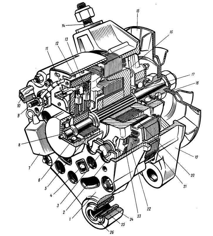
Figure 127. Generator 37.3701: 1 - cover from the contact ring side; 2 - rectifier block; 3 - valve (diode) of the rectifier block; 4 - rectifier block mounting screw; 5 - contact ring; 6 - rear ball bearing; 7 - capacitor; 8 - rotor shaft; 9 - terminal "30" of the generator; 10 - output "61" of the generator; 11 - terminal "B" of the voltage regulator; 12 - voltage regulator; 13 - brush; 14 - generator mounting stud to tension bar; 15 - pulley with fan; 16 - rotor pole tip; 17 - spacer sleeve; 18 - Front ball bearing; 19 - drive side cover; 20 - rotor winding; 21 - stator; 22 - stator winding; 23 - rotor pole tip; 24 - buffer bushing; 25 - bushing; 26 - pressure sleeve
Three-phase alternating current induced in the stator winding is converted into direct current by rectifier unit 2, attached to cover 1. Electronic regulator 12 is combined into one unit with a brush holder and is also attached to cover 1.
The circuit diagram of the generator is shown in Figure 128. The voltage for driving the generator when the ignition is turned on is supplied to the terminal "B" of the regulator through the control lamp 7 and resistors 4 connected in parallel. After starting the motor, the drive winding is powered from three additional diodes installed on the rectifier unit. At the same time, the current does not pass through the control lamp and it does not light up. The control voltage no is given to the output "6" of the regulator directly from the terminal "30" of the generator. The output of the bus controller is not marked. The brush 18 is connected to it (see figure 127). Brief technical characteristics of the generator:
- Maximum output current at 13 V and rotor speed of 5000 rpm - A 55
- Adjustable voltage limits, V — 1-1.1±0.5
- Maximum rotor speed, rpm - 13,000
- The gear ratio between the crankshaft and the generator is 1:2.04
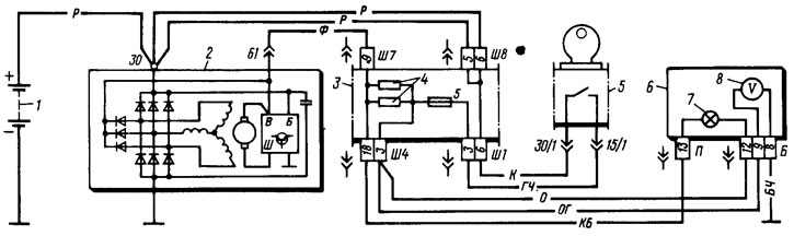
Figure 128. Generator connection diagram: 1 - battery; 2 - generator; 3 - mounting block (fragment); 4 - additional resistors of 100 Ohm, 2 W; 5 - ignition switch (fragment); 6 - instrument cluster (fragment); 7 - Low battery indicator lamp; 8 - voltmeter