
Stator 21 (pic. 7-3) and covers 1 and 19 are tightened with four bolts. The shaft 8 of the rotor rotates in bearings 6 and 18, which are installed in the covers. Power to the rotor winding (excitation winding) supplied through brushes and slip rings 5.
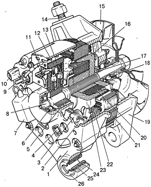
Pic. 7-3. Generator 37.3701:
1 - cover from the side of slip rings; 2 - rectifier block; 3 - rectifier block valve; 4 - screw for fastening the rectifier unit; 5 - contact ring; 6 - rear ball bearing; 7 - capacitor; 8 - rotor shaft; 9 - output «30» generator; 10 - output «61» generator; 11 - output «IN» voltage regulator; 12 - voltage regulator; 13 - brush; 14 - stud fastening the generator to the tension bar; 15 - a pulley with a fan; 16 - pole tip of the rotor; 17 - remote bushing; 18 - front ball bearing; 19 - cover on the drive side; 20 - rotor winding; 21 - stator; 22 - stator winding; 23 - pole tip of the rotor; 24 - buffer sleeve; 25 - bushing; 26 - clamping sleeve.
The three-phase alternating current induced in the stator winding is converted into a direct current by a rectifier unit 2 attached to the cover 1. The electronic voltage regulator 12 is combined into one unit with a brush holder and is also attached to the cover 1.
The generator connection diagram is shown in fig. 7-4. The voltage to excite the generator when the ignition is turned on is supplied to the output «IN» regulator (conclusion «61» generator) through fuse 2 and control lamp 6 located in the instrument cluster 3. After starting the engine, the field winding is powered by three additional diodes installed on the rectifier unit of the generator.
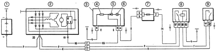
Pic. 7-4. Generator connection diagram:
1 - battery; 2 - generator; 3 - instrument cluster; 4 - resistor 51 Ohm, 5 W; 5 - diode; 6 - control lamp of the battery charge; 7 - fuse box; 8 - ignition relay; 9 - ignition switch.
The operation of the generator is controlled by a control lamp 6 in the instrument cluster. When the ignition is turned on, the lamp should be on, and after starting the engine, it should go out if the generator is working. The bright burning of the lamp or its glow at full heat indicates a malfunction in the generator system.
Until 1995, the voltage in the vehicle's electrical system was monitored by an electronic voltmeter in the instrument cluster. When it was normal, the voltmeter LED did not light up. If the voltage was above the norm, the LED blinked, and if it was low, it glowed constantly.
Since 1996, the device of the voltage regulator and brush holder has been changed. Now the voltage regulator is placed in a metal case and riveted to the brush holder (pic. 7-10, a), i.e. forms a non-separable knot with it. The new voltage regulator is missing a pin «B», and voltage is applied only to the output «IN». According to their characteristics, the old and new voltage regulators are the same and, assembled with a brush holder, are interchangeable.
Alternators manufactured in Slovenia, Bulgaria or Germany may be installed on some vehicles. These generators are interchangeable with the 37.3701 generator in terms of characteristics and installation dimensions, but differ somewhat in design. This chapter describes only the domestic generator 37.3701, as the main one for VAZ-21213 cars.
Warnings
«Minus» battery must always be connected to «weight», A «plus» - connect to clamp «30» generator. An erroneous reverse connection of the battery will immediately cause increased current through the generator valves, and they will be damaged.
The generator must not be operated with the battery disconnected. This will cause transient overvoltages on the terminal «30» generator, which can damage the generator voltage regulator and electronic devices in the vehicle's on-board network.
It is forbidden to check the operability of the generator «for a spark» even short-term clamp connection «30» generator with «weight». In this case, a significant current flows through the valves, and they are damaged. You can only check the generator with an ammeter and a voltmeter.
It is not allowed to check the generator valves with a voltage of more than 12 V or with a megohmmeter, since it has a voltage too high for the valves, and they will be broken during the test (a short circuit will occur).
It is forbidden to check the car's electrical wiring with a megohmmeter or a lamp powered by a voltage of more than 12 V. If such a check is necessary, then first disconnect the wires from the generator.
It is necessary to check the insulation resistance of the generator stator winding with increased voltage only at the stand and always with the phase winding leads disconnected from the valves.
When welding components and parts of the car body, disconnect the wires from all the terminals of the generator and the battery.