
Checking the generator on the stand
Allows you to determine the serviceability of the generator and the compliance of its characteristics with the nominal ones. The brushes of the generator under test must be well ground to the contact rings, and the rings themselves must be clean.
Install the generator on the stand and make connections as shown in fig. 129. Turn on the electric motor of the stand, set the voltage at the output of the generator to 13 V with a rheostat 5 and adjust the rotor speed to 5000 rpm. Let the generator run in this mode for at least 2 minutes, and then measure the recoil current. For a working generator, it should be at least 55 A.
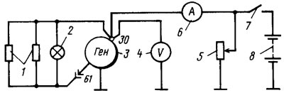
Pic. 129. Wiring diagram for testing the generator on the stand: 1 - resistors of 100 Ohm, 2 W; 2 - control lamp 12 V, 1.2 W; 3 - generator; 4 - voltmeter; 5 - rheostat; 6 - ammeter; 7 - switch; 8 - battery
If the measured value of the output current is less, then this indicates a malfunction in the stator or rotor windings, damage to the valves or wear of slip rings and brushes. In this case, a thorough inspection of the windings and valves is necessary to determine the location of the fault.
The voltage at the generator output is checked at a rotor speed of 5000 rpm. Rheostat 5 sets the recoil current of 15 A and measures the voltage at the generator output, which should be (14,1±0,5) At ambient temperature and generator (25±10) °C.
If the voltage does not fit within the specified limits, then replace the voltage regulator with a new one, known to be good, and repeat the test. If the voltage is normal, then the old voltage regulator is damaged and must be replaced. And if the voltage still does not fit within the above limits, then it is necessary to check the windings and generator valves.
Checking the excitation winding of the rotor
The excitation winding can be checked without removing the generator from the car, removing only the voltage regulator together with the brush holder. Having cleaned, if necessary, the contact rings with a sandpaper, an ohmmeter or a test lamp, check if there is an open in the excitation winding and if it closes to the case.
Stator check
The stator is checked separately after disassembling the generator. Its winding leads must be disconnected from the rectifier valves. First of all, they check with an ohmmeter or with the help of a test lamp and a battery, whether there are breaks in the stator winding and whether its turns close to the housing.
The insulation of the winding wires must be free from overheating, which occurs during a short circuit in the rectifier valves. A stator with such a damaged winding should be replaced. Then they check with a special flaw detector whether there are short-circuited turns in the stator winding.
Checking the rectifier valves
A good valve only allows current to flow in one direction, a bad valve may not allow current to flow at all (open circuit) or pass current in both directions (short circuit). If one of the rectifier valves is damaged, the entire rectifier unit must be replaced.
A short circuit in the valves can be checked without removing the alternator from the vehicle by first disconnecting the wires from the battery and the alternator. Also disconnect the output «b» voltage regulator from terminal «30» generator and wire from the output «IN» voltage regulator. You can check with an ohmmeter or with a lamp (1-5W, 12V) and battery as shown in Fig. 130.
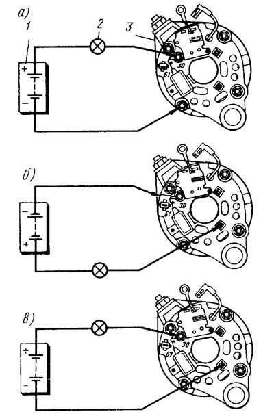
Fig 130. Schemes for checking rectifier valves: a - checking both positive and negative valves; b - checking the negative valves; c - checking the positive valves; 1 - battery; 2 - control lamp; 3 - generator
In order to simplify the fastening of parts of the rectifier, three valves have a plus of the rectified current on the case (These are positive polarity valves). They are pressed into one plate of the rectifier block, connected to the output «30» generator. Other three gates (negative) have a minus rectified current on the case. They are pressed into another plate of the rectifier unit connected to ground.
First, it is checked that the short circuits are simultaneously in the positive and negative valves. To do this, plus the batteries through the lamp are connected to the clamp «30» generator, and minus - to the generator housing (pic. 130,a). If the lamp is on, then both the negative and positive valves are shorted.
You can check the short circuit of the negative valves by connecting the plus of the batteries through the lamp to one of the bolts securing the rectifier unit, and the minus to the generator housing (pic. 130.6). A lamp on indicates a short circuit in one or more of the negative valves. It should be remembered that in this case, the burning of the lamp may be due to the short circuit of the turns of the stator winding on the generator housing. However, such a malfunction is less common than a short circuit of the valves.
To check for a short circuit in the positive valves, the batteries are connected through a lamp to the clamp «30» generator, and minus the battery - with one of the bolts for fastening the rectifier unit (pic. 130,in). A burning lamp will indicate a short circuit in one or more of the positive valves.
Without disassembling the generator, a break in the valves can only be detected indirectly when checking the generator on the stand for a significant reduction (by 20-30%) the strength of the given current compared to the nominal. If the windings, additional diodes and the generator voltage regulator are in good condition, and there is no short circuit in the valves, then the reason for the decrease in the output current is an open in the valves.
Checking additional diodes
A short circuit of additional diodes can be checked without removing and disassembling the generator by disconnecting the wires from the battery and the generator and the wire from the output «IN» voltage regulator.
Plus batteries through the lamp (1-3W, 12V) add to conclusion «61» generator, and minus the battery - to one of the bolts securing the rectifier unit. If the lamp lights up, then there is a short circuit in one of the additional diodes. You can find a damaged diode only by removing the rectifier unit and checking each diode individually.
An open in additional diodes can be detected with an oscilloscope by distorting the voltage curve on the plug «61», as well as low voltage (below 14 V) on plug «61» at an average frequency of rotation of the generator rotor.