
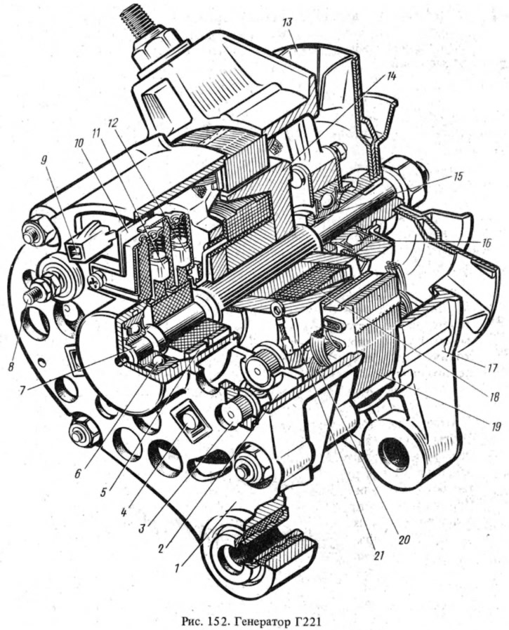
The main parts of the generator are a stator 19 with two covers and made of aluminum alloy, tightened with four bolts, and a rotor with a winding 18. The rotor rotates in two closed ball bearings 6 and 16. Grease is put into the bearings during their manufacture and does not require replenishment during operation. The inner race of the bearing 16, together with the distance ring 15, is clamped between the pulley hub and the shaft shoulder with the help of the pulley fastening nut.
The generator rotor is driven by pulley 13 using a V-belt drive from the crankshaft pulley. The rotor consists of a shaft 7, on which a steel bushing and steel beak-shaped poles 14 and 21 are pressed, forming together with the shaft and bushing the core of the electromagnet. On a steel sleeve between the beak-shaped poles in a plastic frame, the winding 18 of the rotor is wound, called the excitation winding. The ends of the winding are connected to contact rings 5 mounted on a plastic block pressed onto the rotor shaft.
The current to the excitation winding is supplied through brushes 11 and 12, pressed by springs to slip rings. The brushes are made of a copper-graphite mixture and are located in a plastic brush holder 10. One of the brushes is connected to the generator housing, and the other to the plug "67".
The stator 19 is assembled from plates of electrical steel 1 mm thick. The plates are connected by electric welding. On the inside of the stator there are 36 semi-closed slots, insulated with varnish or electrical insulating cardboard. In these grooves, a three-phase winding 20 is laid, secured from falling out with wooden wedges or plastic tubes. Each phase winding consists of six continuously wound coils. The phase windings are connected in a star with the output 9 of the zero point. The relay of a control lamp of a charge of the accumulator battery is connected to it.
The alternating voltage induced in the stator winding is converted into a constant voltage by a rectifier assembled on six silicon valves of the VA-20 type in a three-phase bridge circuit. In order to simplify the details of fastening the rectifier, three valves have a plus of the rectified current on the case (these are direct polarity valves - positive), and three valves - minus the rectified current (reverse polarity valves - negative).
Negative gates 5 (marked with black paint) pressed into the cover of 1 generator, and the positive (marked with red paint) - into a special plate-radiator 2, fixed with screws 4.
A rectifier block is installed on the part of the generators, consisting of two plates with valves pressed into them.
The wiring diagram of the generating set is shown in fig. 153.
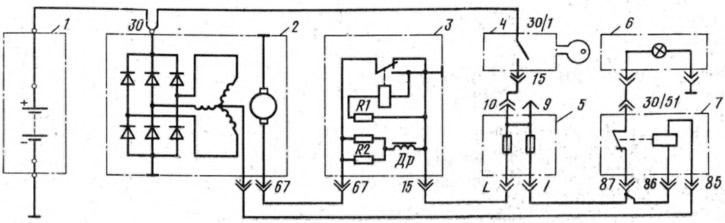
Pic. 153. Connection diagram of the generator set:
1 - battery; 2 - generator; 3 - voltage regulator; 4 - ignition switch; 5 - fuse box; b - charge control lamp; 7 - charge control lamp relay.
Brief technical characteristics of the generator:
- Maximum recoil current at 14 V and rotor speed 5000 rpm, A - 42
- Maximum rotor speed, rpm — 13,000
- The gear ratio between the crankshaft and the generator is 1:2.04